
7-150
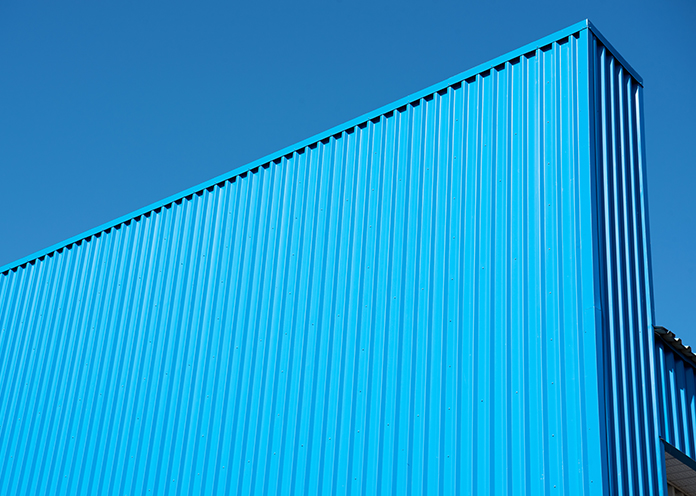
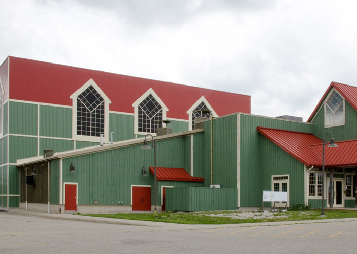
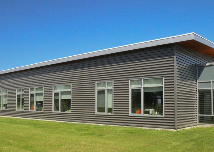
An Exposed Fastener System, the 7-150 profile demonstrates the versatility of Agway profile designs as it can be used as a roof or wall cladding. Moreover, its load bearing capabilities enable 7-150 system components to function as a structural members. An economical system that’s very easy to install have made 7-150 a popular choice for industrial and commercial applications.
Agway 7-150 comes in a full range of stock colours, with colour matched fasteners, trims and accessories.
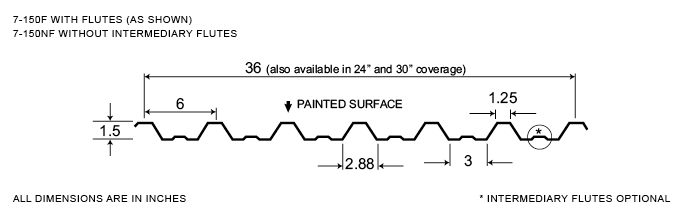
Measurement Type
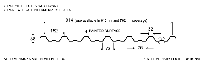
Profile Picture
1. Steel conforms to ASTM A653.
2. Section properties are in accordance with CSA-S136-07.
3. Values in row “S” are based on strength.
4. Values in row “D” are based on a deflection limit of 1/180 of the span.
5. Web crippling not included in strength values. See example calculation in notes to designer.
6. Contact the sales department for stocked colours and gauges.
7. The load table contained on this data sheet was prepared by Dr. R.M. Schuster P.Eng. Professor Emeritus of Structural Engineering, University of Waterloo, Ontario, Canada.
Specifications
| GAUGE | LENGTH | COVERAGE | ||
|---|---|---|---|---|
| MINIMUM | MAXIMUM | MINIMUM | MAXIMUM | |
| 26 | 20 | 10 | 780 | 36 |
| 26 | 20 | 10 | 780 | 30 |
| 26 | 20 | 10 | 780 | 24 |
| GAUGE | LENGTH | COVERAGE | ||
|---|---|---|---|---|
| MINIMUM | MAXIMUM | MINIMUM | MAXIMUM | |
| 26 | 20 | 254 | 19.81 | 914 |
| 26 | 20 | 254 | 19.81 | 780 |
| 26 | 20 | 254 | 19.81 | 610 |
Section Properties
| BASE STEEL THICKNESS |
WEIGHT G90 |
YIELD STRESS |
SECTION MODULUS |
DEFLECTION MOMENT OF INERTIA |
|
|---|---|---|---|---|---|
| in | psf | ksi | MID SPAN in 3 |
SUPPORT in 3 |
MID SPAN in 4 |
| 0.018 | 1.04 | 33 | 0.0940 | 0.0888 | 0.0985 |
| 0.024 | 1.36 | 33 | 0.136 | 0.127 | 0.132 |
| 0.030 | 1.69 | 33 | 0.175 | 0.162 | 0.165 |
| 0.036 | 2.02 | 33 | 0.208 | 0.198 | 0.197 |
| BASE STEEL THICKNESS |
MASS Z275 |
YIELD STRESS |
SECTION MODULUS |
DEFLECTION MOMENT OF INERTIA |
|
|---|---|---|---|---|---|
| mm | kg/m | MPa | MID SPAN x10 3mm3 |
SUPPORT x10 3mm3 |
MID SPAN x10 3mm3 |
| 0.457 | 5.06 | 230 | 5.05 | 4.77 | 0.134 |
| 0.610 | 6.66 | 230 | 7.28 | 6.82 | 0.180 |
| 0.762 | 8.25 | 230 | 9.38 | 8.73 | 0.225 |
| 0.914 | 9.85 | 230 | 11.2 | 10.7 | 0.270 |
