RD36 | RD36 CL
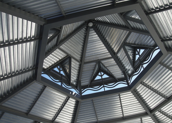
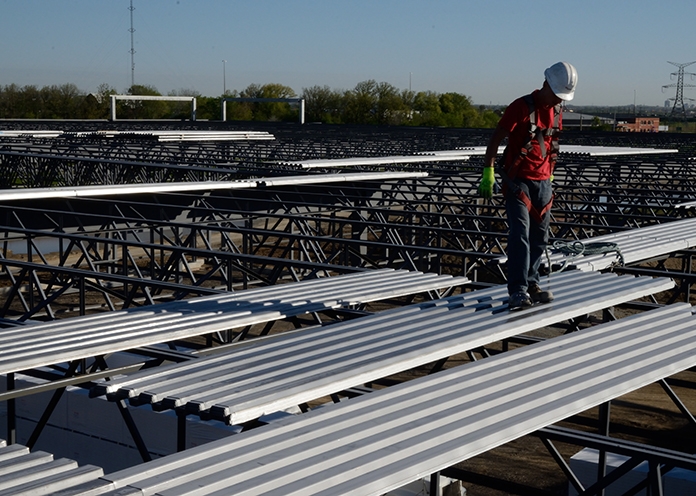
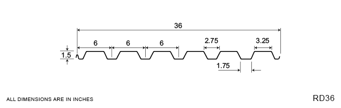
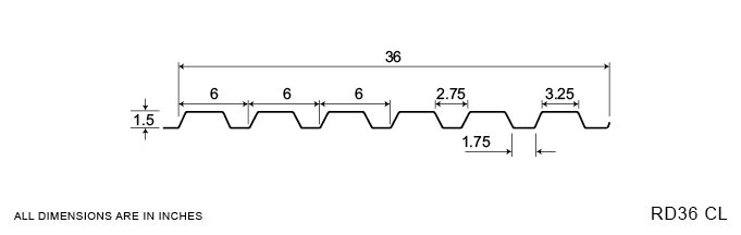
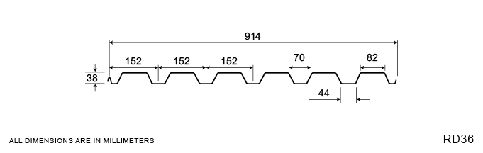
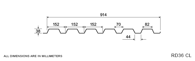
The RD36 profile is Agway’s most popular roof deck section and is the preferred deck section for industrial/commercial applications.
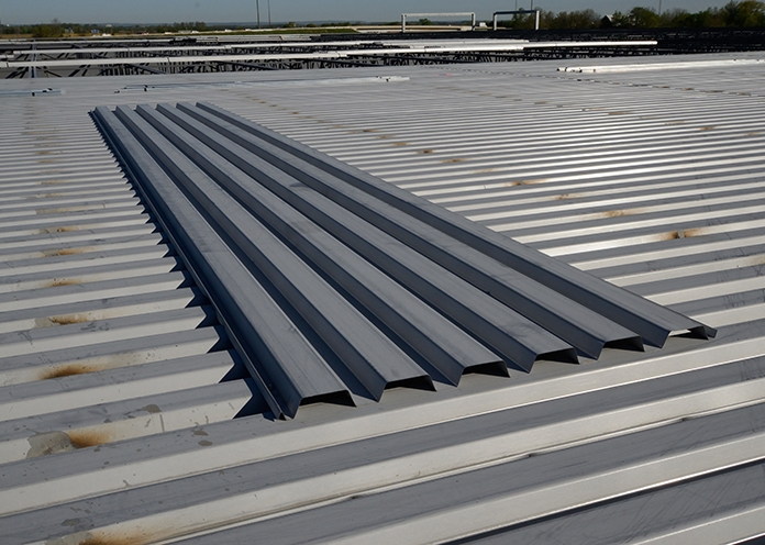
Our structural roof deck sections are available in a wide range of gauges in Galvanneal, galvanized or prepainted finishes: these options enable customers to determine the optimal combination of strength, performance, and affordability that best satisfies project-specific criteria. Agway roof deck sections are also available in an acoustic format with pre-punched holes in the webs of the deck which combine with acoustic batt insulation to significantly reduce ambient noise within a structure.
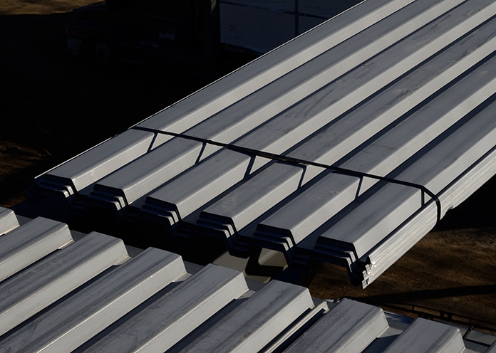
Bundled deck produced from either Galvanneal or G90 Galvanized coated steel is susceptible to storage stain when exposed to the elements. This staining is superficial only and is not a valid reason for rejection of this product.
For more information, refer to CSSBI Fact Sheet #33
Measurement Type
Profile Picture
1. Steel conforms to ASTM A653.
2. Section properties are in accordance with CSA-S136-07.
3. Values in row “S” are based on strength.
4. Values in row “D” are based on a deflection limit of 1/240 of the span.
5. Web crippling not included in strength values. See example calculation in notes to designer.
6. Contact the sales department for stocked colours and gauges.
7. The load table contained on this data sheet was prepared by Dr. R.M. Schuster P.Eng. Professor Emeritus of Structural Engineering, University of Waterloo, Ontario, Canada.
Specifications
| GAUGE | LENGTH | COVERAGE | ||
|---|---|---|---|---|
| MINIMUM | MAXIMUM | MINIMUM | MAXIMUM | |
| 22 | 16 | 36" | 540" | 36" |
| GAUGE | LENGTH | COVERAGE | ||
|---|---|---|---|---|
| MINIMUM | MAXIMUM | MINIMUM | MAXIMUM | |
| 22 | 16 | 914 mm | 13.72 m | 914 mm |
Section Properties
| BASE STEEL THICKNESS |
WEIGHT G90 |
YIELD STRESS |
SECTION MODULUS |
DEFLECTION MOMENT OF INERTIA |
|
|---|---|---|---|---|---|
| in | psf | ksi | MID SPAN in 3 |
SUPPORT in 3 |
MID SPAN in 4 |
| 0.030 | 1.69 | 33 | 0.184 | 0.194 | 0.163 |
| 0.036 | 2.02 | 33 | 0.226 | 0.233 | 0.204 |
| 0.048 | 2.68 | 33 | 0.307 | 0.315 | 0.208 |
| 0.060 | 3.33 | 33 | 0.387 | 0.389 | 0.349 |
| BASE STEEL THICKNESS |
MASS Z275 |
YIELD STRESS |
SECTION MODULUS |
DEFLECTION MOMENT OF INERTIA |
|
|---|---|---|---|---|---|
| mm | kg/m | MPa | MID SPAN x10 3mm3 |
SUPPORT x10 3mm3 |
MID SPAN x10 3mm3 |
| 0.762 | 8.27 | 230 | 9.89 | 10.4 | 0.223 |
| 0.914 | 9.86 | 230 | 12.1 | 12.5 | 0.278 |
| 1.22 | 13.1 | 230 | 16.5 | 16.9 | 0.382 |
| 1.52 | 16.3 | 230 | 20.8 | 20.9 | 0.476 |
