Product Sheet
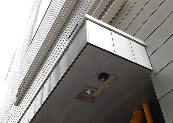
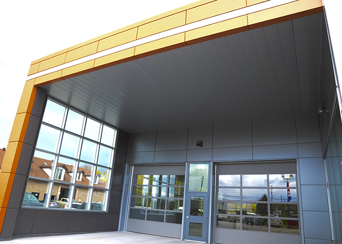
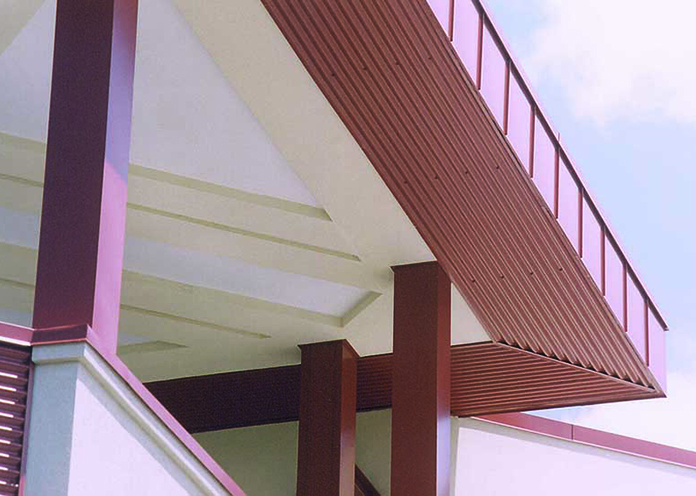
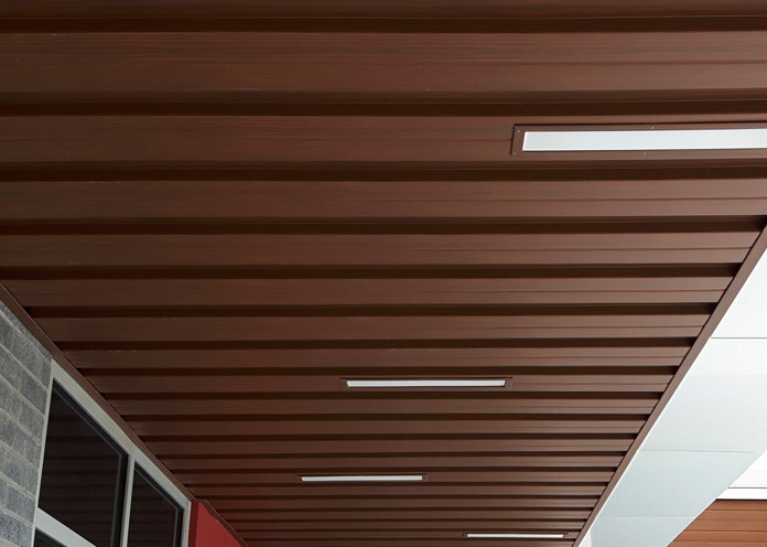
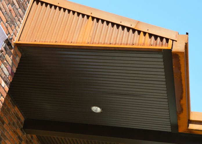
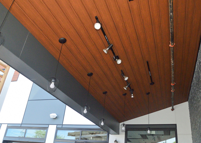
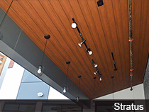
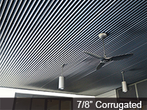
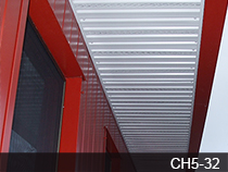
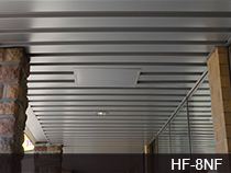
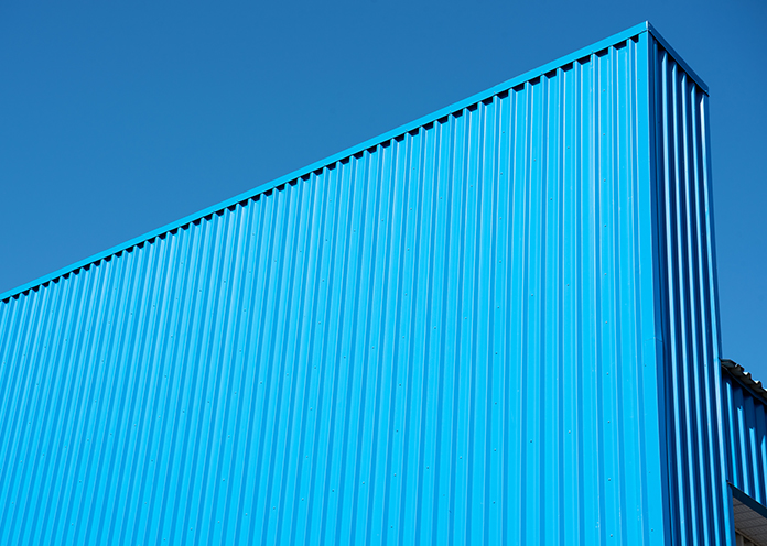
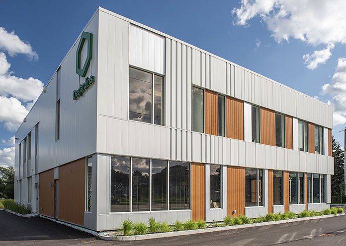
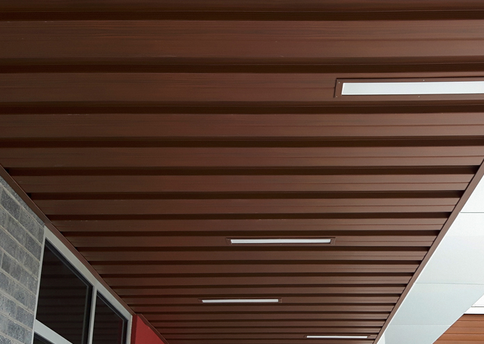
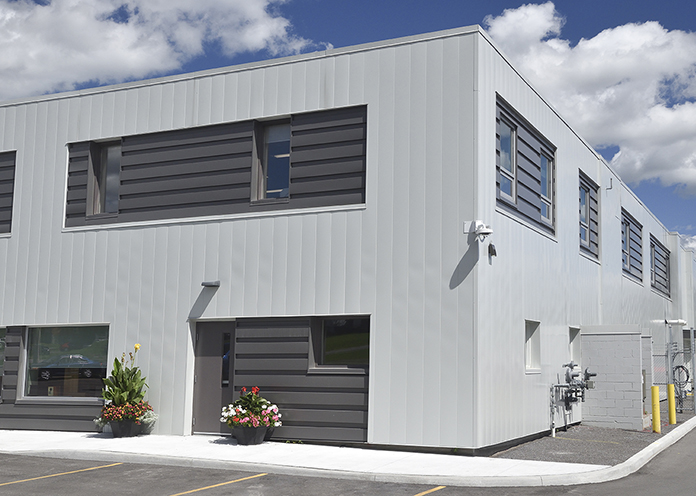
ICI Soffits
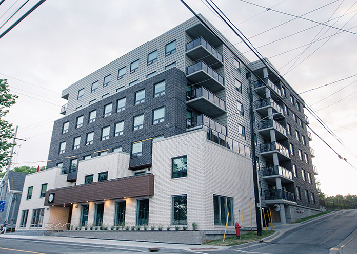
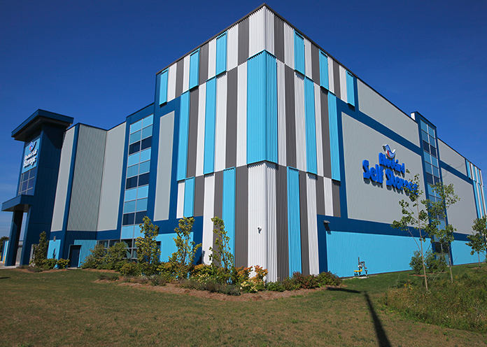
Easy to handle and install with multiple products to choose from (including custom flat panels), Agway’s ICI soffit panels are available in custom lengths and a full choice of stock or custom colours and finishes.
- Multiple products to choose from including custom flat panels
- Full choice of any stock or custom colour
- Plain or Pre-painted Steel, Aluminum, Copper, Stainless Steel, Rheinzink and Indaten
- Pre-cut to required length – no field cutting
- Attractive appearance
- Easy installation – Exposed or Hidden fastener profiles available
- Perforated or Non-Perforated available
Measurement Type
Product Sheet
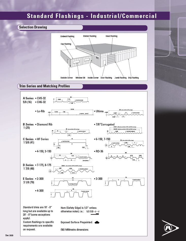
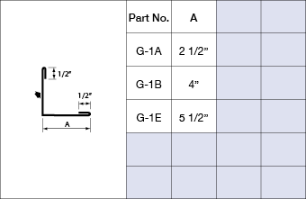
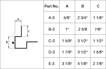
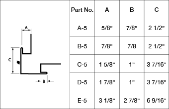
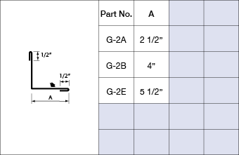
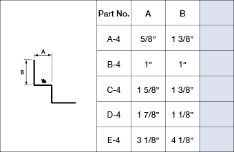
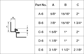
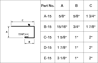
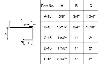
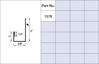
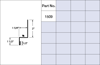
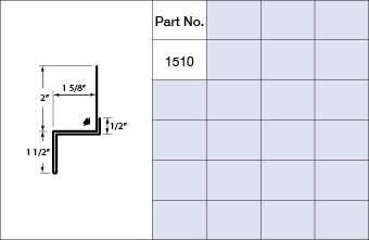
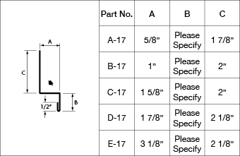
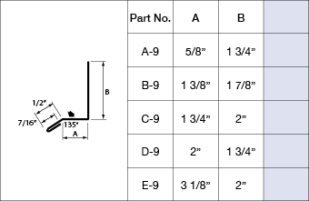
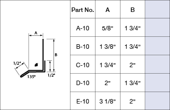
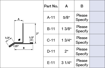
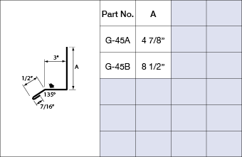
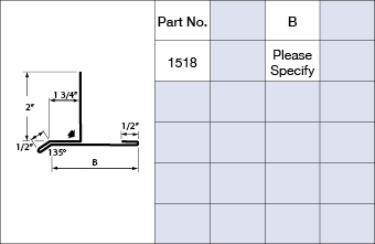
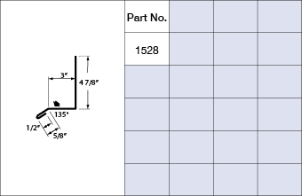
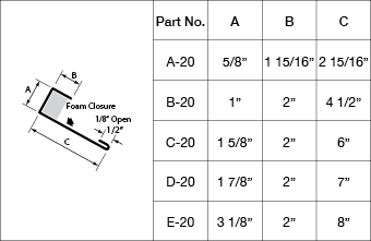
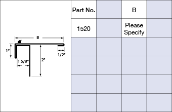
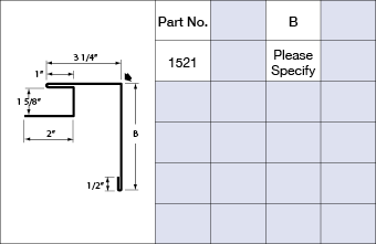
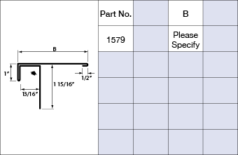
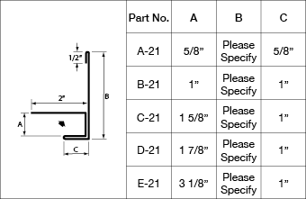
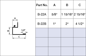
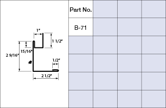
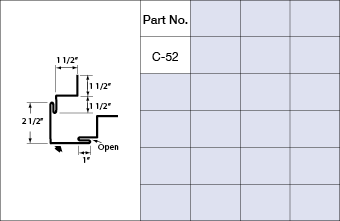
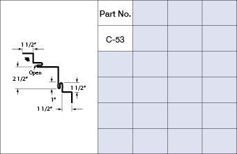
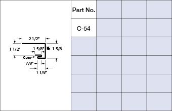
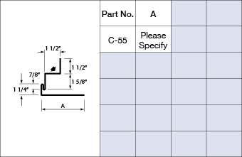
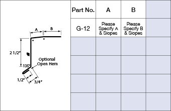
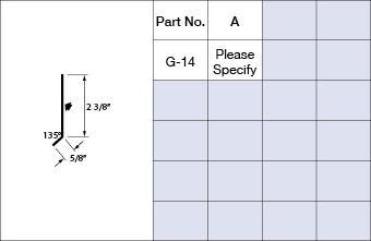
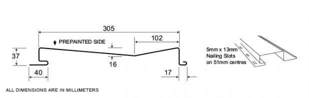
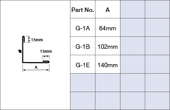
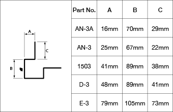
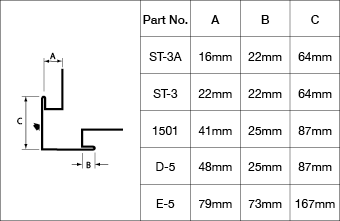
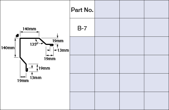
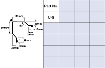
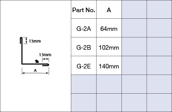
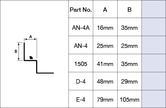
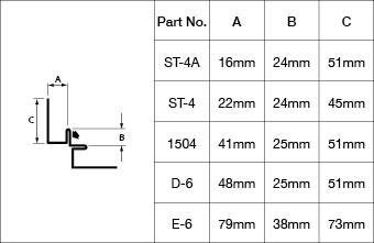
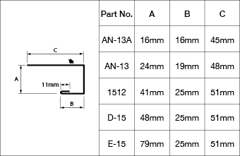
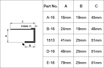
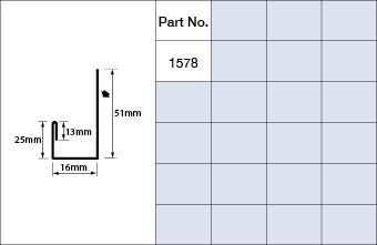
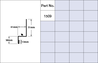
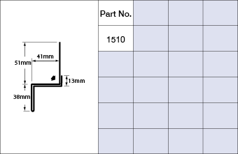
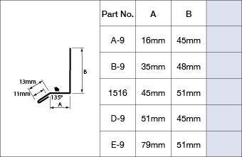
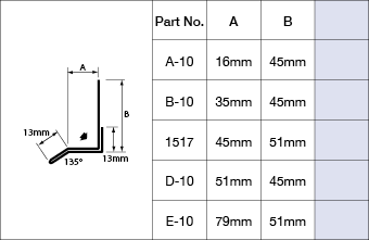
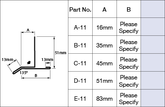
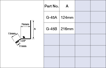
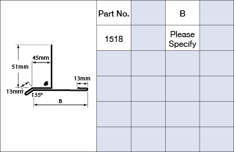
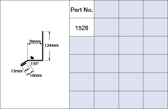
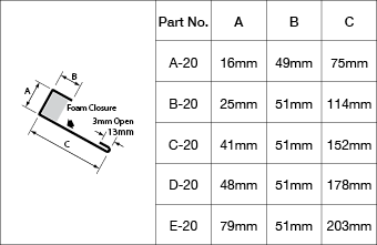
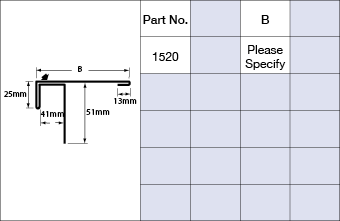
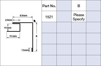
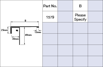
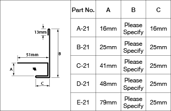
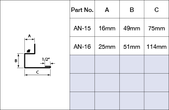
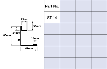
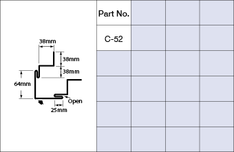
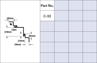
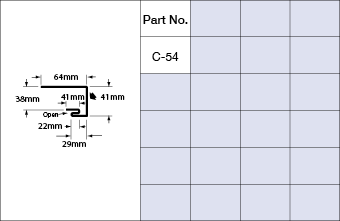
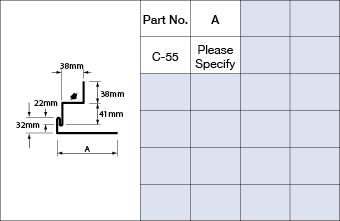
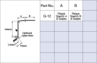
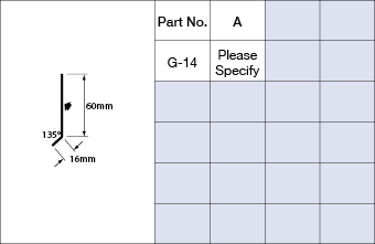
Standard Flashings ICI
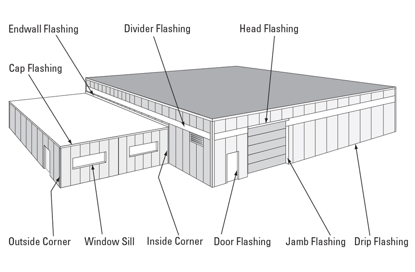
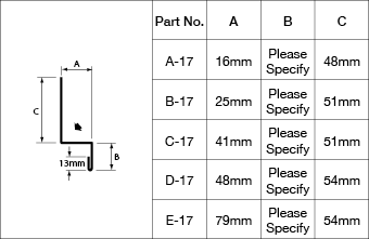
If there is a shape of flashing you need, we can bend it. Agway offers everything required in flashings and trims to complete your industrial and/or commercial building installation. From Outside Corners to Jambs & Coping Flashing, Agway has it all.
Measurement Type
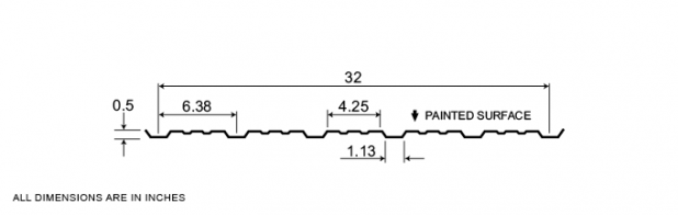
Profile Picture
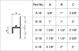
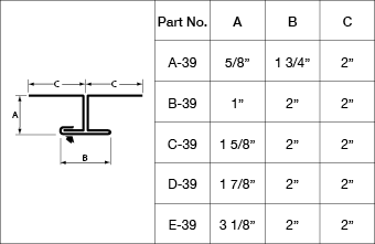
A SERIES 5/8 in
B SERIES 1 in
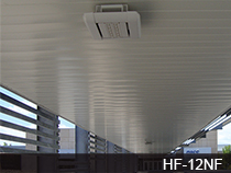
C SERIES 1 5/8 in


D SERIES 1 7/8 in
E SERIES 3 1/8 in
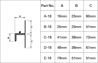
Typical Flashings
OUTSIDE CORNERS


INSIDE CORNERS
J-TRIMS
BASE TRIMS
DRIPS
DIVIDERS
TOP CLOSURES
JAMBS
HIDDEN FASTENERS
WINDOW SILLS
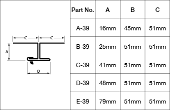
A SERIES 16 mm

B SERIES 25 mm
C SERIES 41 mm

D SERIES 48 mm
E SERIES 79 mm
Typical Flashings
OUTSIDE CORNERS
INSIDE CORNERS
J-TRIMS
BASE TRIMS
DRIPS
DIVIDERS
TOP CLOSURES
JAMBS
HIDDEN FASTENERS
WINDOW SILLS

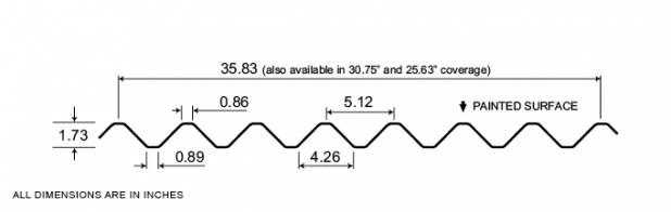
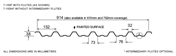
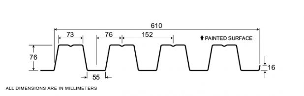
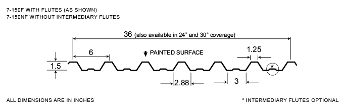
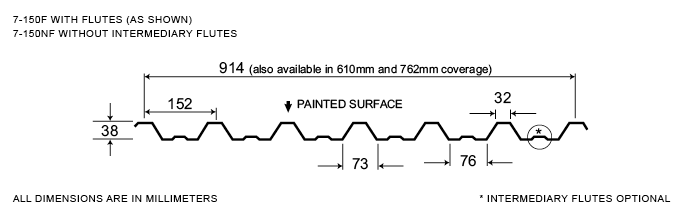
7-150
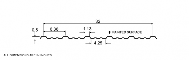
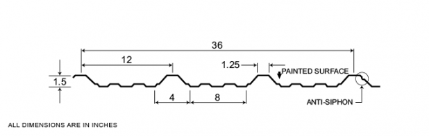
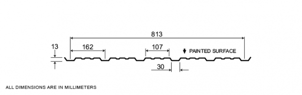
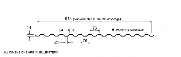
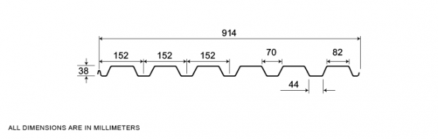
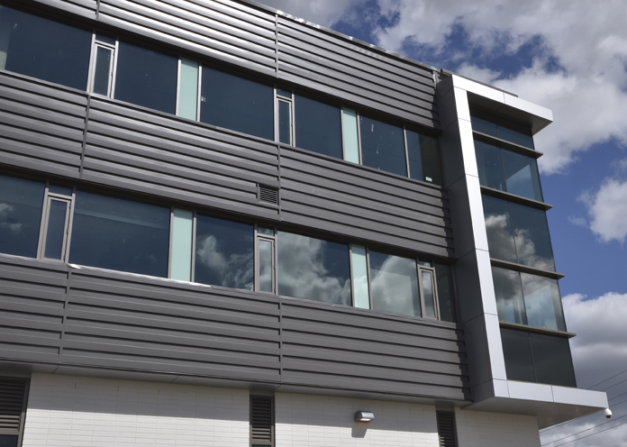
An Exposed Fastener System, the 7-150 profile demonstrates the versatility of Agway profile designs as it can be used as a roof or wall cladding. Moreover, its load bearing capabilities enable 7-150 system components to function as a structural members. An economical system that’s very easy to install have made 7-150 a popular choice for industrial and commercial applications.
Agway 7-150 comes in a full range of stock colours, with colour matched fasteners, trims and accessories.
Measurement Type
Profile Picture
1. Steel conforms to ASTM A653.
2. Section properties are in accordance with CSA-S136-07.
3. Values in row “S” are based on strength.
4. Values in row “D” are based on a deflection limit of 1/180 of the span.
5. Web crippling not included in strength values. See example calculation in notes to designer.
6. Contact the sales department for stocked colours and gauges.
7. The load table contained on this data sheet was prepared by Dr. R.M. Schuster P.Eng. Professor Emeritus of Structural Engineering, University of Waterloo, Ontario, Canada.
Specifications
| GAUGE | LENGTH | COVERAGE | ||
|---|---|---|---|---|
| MINIMUM | MAXIMUM | MINIMUM | MAXIMUM | |
| 26 | 20 | 10 | 780 | 36 |
| 26 | 20 | 10 | 780 | 30 |
| 26 | 20 | 10 | 780 | 24 |
| GAUGE | LENGTH | COVERAGE | ||
|---|---|---|---|---|
| MINIMUM | MAXIMUM | MINIMUM | MAXIMUM | |
| 26 | 20 | 254 | 19.81 | 914 |
| 26 | 20 | 254 | 19.81 | 780 |
| 26 | 20 | 254 | 19.81 | 610 |
Section Properties
| BASE STEEL THICKNESS |
WEIGHT G90 |
YIELD STRESS |
SECTION MODULUS |
DEFLECTION MOMENT OF INERTIA |
|
|---|---|---|---|---|---|
| in | psf | ksi | MID SPAN in 3 |
SUPPORT in 3 |
MID SPAN in 4 |
| 0.018 | 1.04 | 33 | 0.0940 | 0.0888 | 0.0985 |
| 0.024 | 1.36 | 33 | 0.136 | 0.127 | 0.132 |
| 0.030 | 1.69 | 33 | 0.175 | 0.162 | 0.165 |
| 0.036 | 2.02 | 33 | 0.208 | 0.198 | 0.197 |
| BASE STEEL THICKNESS |
MASS Z275 |
YIELD STRESS |
SECTION MODULUS |
DEFLECTION MOMENT OF INERTIA |
|
|---|---|---|---|---|---|
| mm | kg/m | MPa | MID SPAN x10 3mm3 |
SUPPORT x10 3mm3 |
MID SPAN x10 3mm3 |
| 0.457 | 5.06 | 230 | 5.05 | 4.77 | 0.134 |
| 0.610 | 6.66 | 230 | 7.28 | 6.82 | 0.180 |
| 0.762 | 8.25 | 230 | 9.38 | 8.73 | 0.225 |
| 0.914 | 9.85 | 230 | 11.2 | 10.7 | 0.270 |

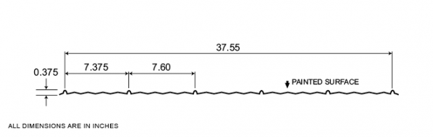
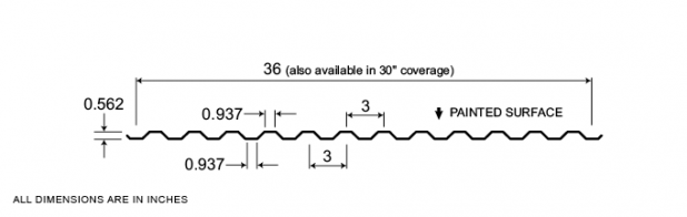
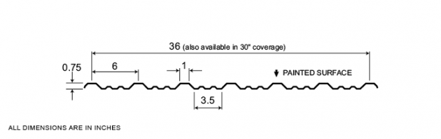
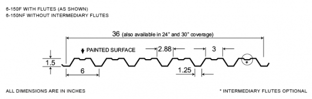
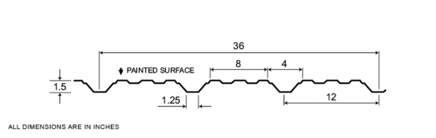
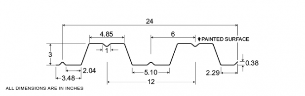
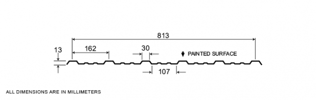
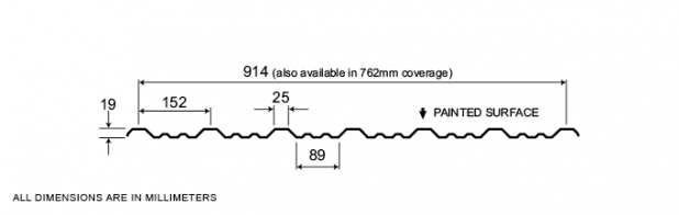
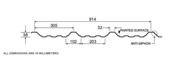
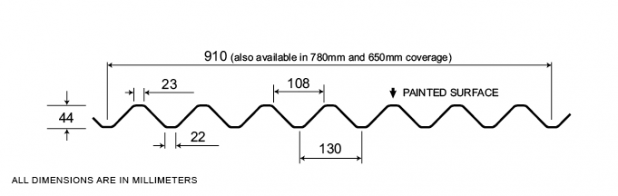
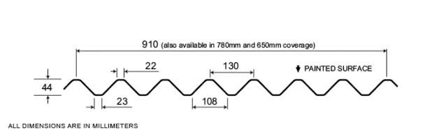
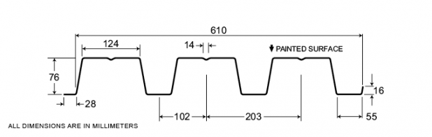
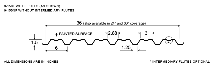
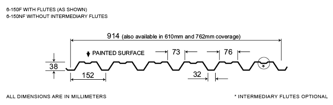
6-150
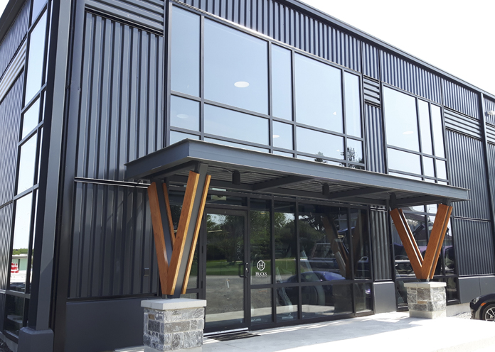
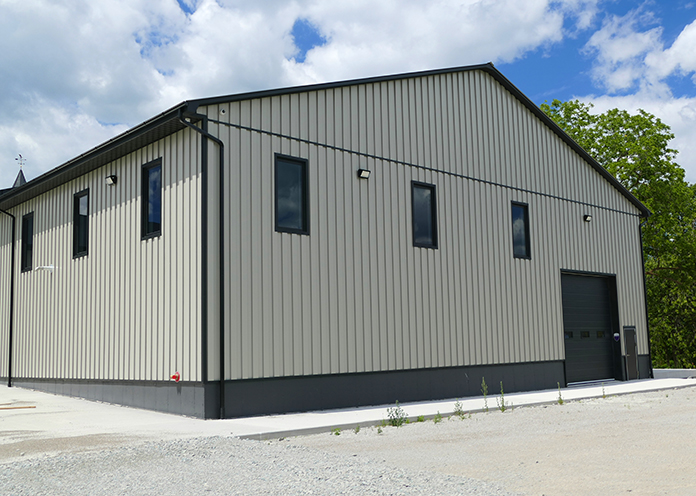
Widely used in industrial and commercial building applications, Agway 6-150 is the most widely used of our Exposed Fastener Series. Panels are available in 24″, 30” and 36” coverage, in a variety of thicknesses and finishes.
Measurement Type
Profile Picture
1. Steel conforms to ASTM A653.
2. Section properties are in accordance with CSA-S136-07.
3. Values in row “S” are based on strength.
4. Values in row “D” are based on a deflection limit of 1/180 of the span.
5. Web crippling not included in strength values. See example calculation in notes to designer.
6. Contact the sales department for stocked colours and gauges.
7. The load table contained on this data sheet was prepared by Dr. R.M. Schuster P.Eng. Professor Emeritus of Structural Engineering, University of Waterloo, Ontario, Canada.
1. Steel conforms to ASTM A653.
2. Section properties are in accordance with CSA-S136-07.
3. Values in row “S” are based on strength.
4. Values in row “D” are based on a deflection limit of 1/180 of the span.
5. Web crippling not included in strength values. See example calculation in notes to designer.
6. Contact the sales department for stocked colours and gauges.
7. The load table contained on this data sheet was prepared by Dr. R.M. Schuster P.Eng. Professor Emeritus of Structural Engineering, University of Waterloo, Ontario, Canada.
Specifications
| GAUGE | LENGTH | COVERAGE | ||
|---|---|---|---|---|
| MINIMUM | MAXIMUM | MINIMUM | MAXIMUM | |
| 26 | 20 | 10 | 780 | 36 |
| 26 | 20 | 10 | 780 | 30 |
| 26 | 20 | 10 | 780 | 24 |
| GAUGE | LENGTH | COVERAGE | ||
|---|---|---|---|---|
| MINIMUM | MAXIMUM | MINIMUM | MAXIMUM | |
| 26 | 20 | 254 | 19.81 | 914 |
| 26 | 20 | 254 | 19.81 | 780 |
| 26 | 20 | 254 | 19.81 | 610 |
Section Properties
| BASE STEEL THICKNESS |
WEIGHT G90 |
YIELD STRESS |
SECTION MODULUS |
DEFLECTION MOMENT OF INERTIA |
|
|---|---|---|---|---|---|
| in | psf | ksi | MID SPAN in 3 |
SUPPORT in 3 |
MID SPAN in 4 |
| 0.018 | 1.04 | 33 | 0.0888 | 0.0940 | 0.0796 |
| 0.024 | 1.36 | 33 | 0.127 | 0.136 | 0.119 |
| 0.030 | 1.69 | 33 | 0.162 | 0.175 | 0.157 |
| 0.036 | 2.02 | 33 | 0.198 | 0.208 | 0.194 |
| BASE STEEL THICKNESS |
MASS Z275 |
YIELD STRESS |
SECTION MODULUS |
DEFLECTION MOMENT OF INERTIA |
|
|---|---|---|---|---|---|
| mm | kg/m | MPa | MID SPAN x10 3mm3 |
SUPPORT x10 3mm3 |
MID SPAN x10 3mm3 |
| 0.457 | 5.06 | 230 | 4.77 | 5.06 | 0.108 |
| 0.610 | 6.66 | 230 | 6.82 | 7.28 | 0.162 |
| 0.762 | 8.25 | 230 | 8.73 | 9.38 | 0.214 |
| 0.914 | 9.85 | 230 | 10.7 | 11.2 | 0.265 |
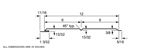
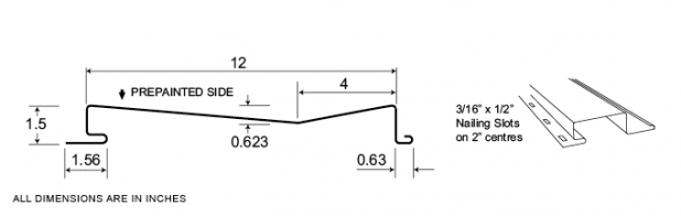
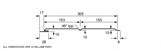
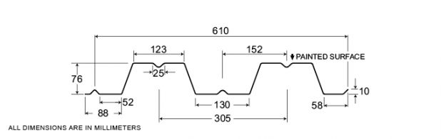
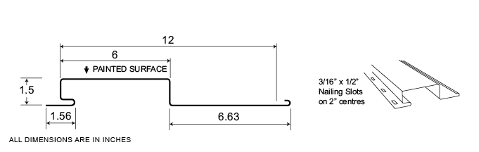
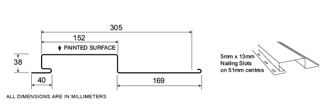
HF-6
Featuring all of the benefits of Agway’s celebrated Hidden Fastener system, the HF-6 profile provides a 12” wide panel with a 6” return and delivers a very distinctive and unique overall appearance, with ultra sleek lines. Ideal for any institutional, industrial or commercial application.
Measurement Type
Profile Picture
1. Steel conforms to ASTM A653.
2. Section properties are in accordance with CSA-S136-07.
3. Values in row “S” are based on strength.
4. Values in row “D” are based on a deflection limit of 1/180 of the span.
5. Web crippling not included in strength values. See example calculation in notes to designer.
6. Oil canning may be present due to thickness and coverage. Oil canning is not a valid reason for rejection of this product.
7. Contact the sales department for stocked colours and gauges.
8. The load table contained on this data sheet was prepared by Dr. R.M. Schuster P.Eng. Professor Emeritus of Structural Engineering, University of Waterloo, Ontario, Canada.
Specifications
| GAUGE | LENGTH | COVERAGE | ||
|---|---|---|---|---|
| MINIMUM | MAXIMUM | MINIMUM | MAXIMUM | |
| 22 | 18 | 10 | 540 | 12 |
| GAUGE | LENGTH | COVERAGE | ||
|---|---|---|---|---|
| MINIMUM | MAXIMUM | MINIMUM | MAXIMUM | |
| 22 | 18 | 254 | 13.72 | 305 |
Section Properties
| BASE STEEL THICKNESS |
WEIGHT G90 |
YIELD STRESS |
SECTION MODULUS |
DEFLECTION MOMENT OF INERTIA |
|
|---|---|---|---|---|---|
| in | psf | ksi | MID SPAN in 3 |
SUPPORT in 3 |
MID SPAN in 4 |
| 0.030 | 1.87 | 33 | 0.0982 | 0.147 | 0.122 |
| 0.036 | 2.23 | 33 | 0.130 | 0.188 | 0.159 |
| 0.048 | 2.96 | 33 | 0.205 | 0.281 | 0.241 |
| BASE STEEL THICKNESS |
MASS Z275 |
YIELD STRESS |
SECTION MODULUS |
DEFLECTION MOMENT OF INERTIA |
|
|---|---|---|---|---|---|
| mm | kg/m | MPa | MID SPAN x10 3mm3 |
SUPPORT x10 3mm3 |
MID SPAN x10 3mm3 |
| 0.762 | 8.85 | 230 | 5.26 | 7.86 | 0.166 |
| 0.914 | 10.6 | 230 | 6.98 | 10.1 | 0.216 |
| 1.22 | 14.2 | 230 | 11.0 | 15.1 | 0.328 |
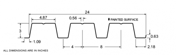
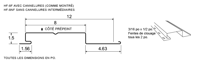
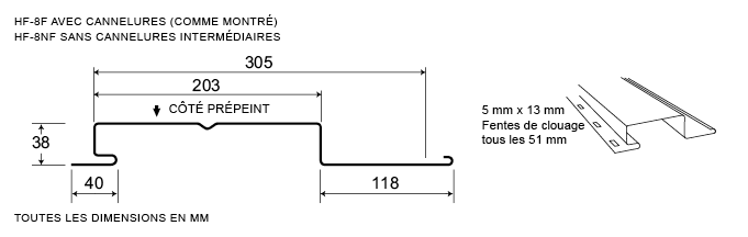
HF-8
Featuring all of the benefits of Agway’s celebrated Hidden Fastener system, the HF-8 provides a 12” wide panel that includes a 4” return, providing a board and batten appearance that is ideal for any institutional, industrial or commercial applications.
Available in a range of gauges and a variety of standard and custom colours, HF-8 enables customers to specify the ideal combination of strength and aesthetics that optimize achievement of all project objectives.
Measurement Type
Profile Picture
1. Steel conforms to ASTM A653.
2. Section properties are in accordance with CSA-S136-07.
3. Values in row “S” are based on strength.
4. Values in row “D” are based on a deflection limit of 1/180 of the span.
5. Web crippling not included in strength values. See example calculation in notes to designer.
6. Oil canning may be present due to thickness and coverage. Oil canning is not a valid reason for rejection of this product.
7. Contact the sales department for stocked colours and gauges.
8. The load table contained on this data sheet was prepared by Dr. R.M. Schuster P.Eng. Professor Emeritus of Structural Engineering, University of Waterloo, Ontario, Canada.
1. Steel conforms to ASTM A653.
2. Section properties are in accordance with CSA-S136-07.
3. Values in row “S” are based on strength.
4. Values in row “D” are based on a deflection limit of 1/180 of the span.
5. Web crippling not included in strength values. See example calculation in notes to designer.
6. Oil canning may be present due to thickness and coverage. Oil canning is not a valid reason for rejection of this product.
7. Contact the sales department for stocked colours and gauges.
8. The load table contained on this data sheet was prepared by Dr. R.M. Schuster P.Eng. Professor Emeritus of Structural Engineering, University of Waterloo, Ontario, Canada.
Specifications
| GAUGE | LENGTH | COVERAGE | ||
|---|---|---|---|---|
| MINIMUM | MAXIMUM | MINIMUM | MAXIMUM | |
| 22 | 18 | 10 | 540 | 12 |
| GAUGE | LENGTH | COVERAGE | ||
|---|---|---|---|---|
| MINIMUM | MAXIMUM | MINIMUM | MAXIMUM | |
| 22 | 18 | 254 | 13.27 | 305 |
Section Properties
| BASE STEEL THICKNESS |
WEIGHT G90 |
YIELD STRESS |
SECTION MODULUS |
DEFLECTION MOMENT OF INERTIA |
|
|---|---|---|---|---|---|
| in | psf | ksi | MID SPAN in 3 |
SUPPORT in 3 |
MID SPAN in 4 |
| 0.030 | 1.87 | 33 | 0.0975 | 0.149 | 0.114 |
| 0.036 | 2.23 | 33 | 0.130 | 0.190 | 0.148 |
| 0.048 | 2.96 | 33 | 0.206 | 0.283 | 0.224 |
| BASE STEEL THICKNESS |
MASS Z275 |
YIELD STRESS |
SECTION MODULUS |
DEFLECTION MOMENT OF INERTIA |
|
|---|---|---|---|---|---|
| mm | kg/m | MPa | MID SPAN x10 3mm3 |
SUPPORT x10 3mm3 |
MID SPAN x10 3mm3 |
| 0.762 | 8.85 | 230 | 5.23 | 7.98 | 0.155 |
| 0.914 | 10.6 | 230 | 6.96 | 10.2 | 0.202 |
| 1.22 | 14.2 | 230 | 11.0 | 15.2 | 0.305 |

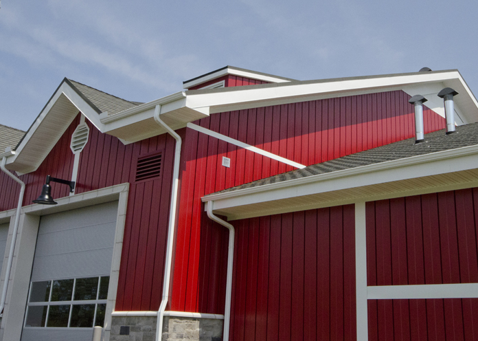
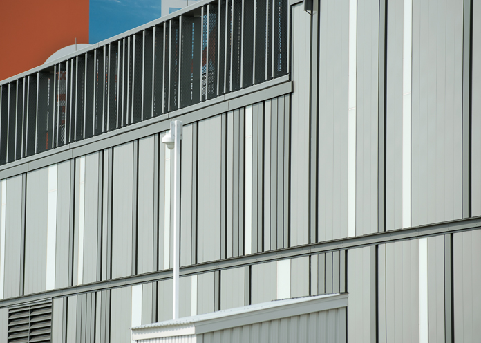
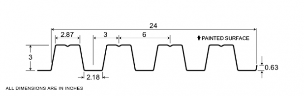
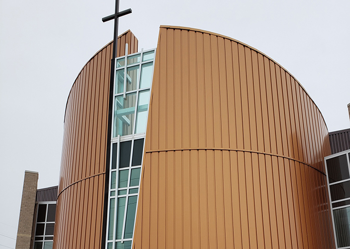
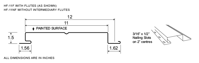
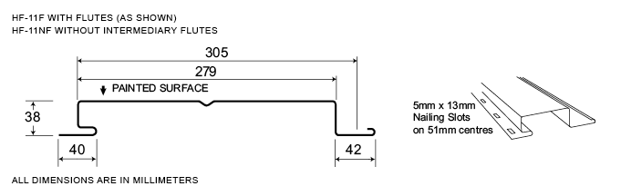
HF-11
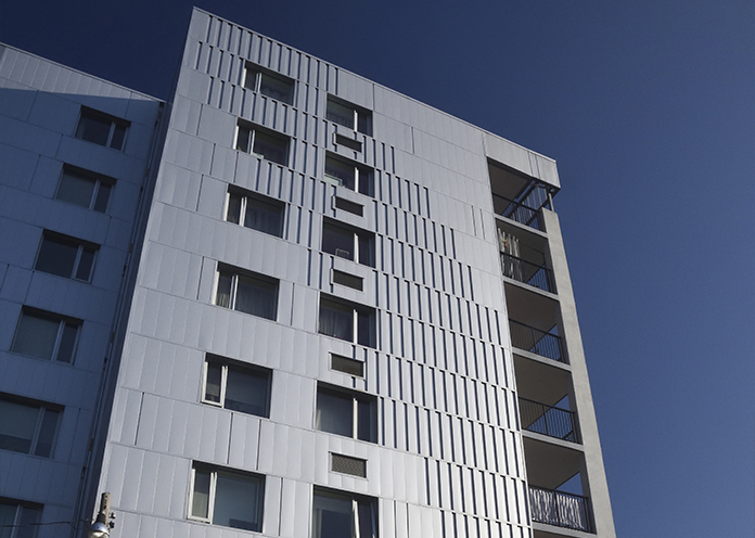
With the introduction of a 1” reveal, the HF-11 profile provides all of the benefits of Agway’s Hidden Fastener series, while delivering the clean, sleek lines of contemporary surfaces popular among architects.
Available in a range of gauges and a variety of standard and custom colours, HF-11 enables customers to specify the ideal combination of strength and aesthetics that optimize achievement of all objectives.
Measurement Type
Profile Picture
1. Steel conforms to ASTM A653.
2. Section properties are in accordance with CSA-S136-07.
3. Values in row “S” are based on strength.
4. Values in row “D” are based on a deflection limit of 1/180 of the span.
5. Web crippling not included in strength values. See example calculation in notes to designer.
6. Oil canning may be present due to thickness and coverage. Oil canning is not a valid reason for rejection of this product.
7. Contact the sales department for stocked colours and gauges.
8. The load table contained on this data sheet was prepared by Dr. R.M. Schuster P.Eng. Professor Emeritus of Structural Engineering, University of Waterloo, Ontario, Canada.
1. Steel conforms to ASTM A653.
2. Section properties are in accordance with CSA-S136-07.
3. Values in row “S” are based on strength.
4. Values in row “D” are based on a deflection limit of 1/180 of the span.
5. Web crippling not included in strength values. See example calculation in notes to designer.
6. Oil canning may be present due to thickness and coverage. Oil canning is not a valid reason for rejection of this product.
7. Contact the sales department for stocked colours and gauges.
8. The load table contained on this data sheet was prepared by Dr. R.M. Schuster P.Eng. Professor Emeritus of Structural Engineering, University of Waterloo, Ontario, Canada.
Specifications
| GAUGE | LENGTH | COVERAGE | ||
|---|---|---|---|---|
| MINIMUM | MAXIMUM | MINIMUM | MAXIMUM | |
| 22 | 18 | 10 | 540 | 12 |
| GAUGE | LENGTH | COVERAGE | ||
|---|---|---|---|---|
| MINIMUM | MAXIMUM | MINIMUM | MAXIMUM | |
| 22 | 18 | 254 | 13.72 | 305 |
Section Properties
| BASE STEEL THICKNESS |
WEIGHT G90 |
YIELD STRESS |
SECTION MODULUS |
DEFLECTION MOMENT OF INERTIA |
|
|---|---|---|---|---|---|
| in | psf | ksi | MID SPAN in 3 |
SUPPORT in 3 |
MID SPAN in 4 |
| 0.030 | 1.87 | 33 | 0.0934 | 0.145 | 0.0926 |
| 0.036 | 2.23 | 33 | 0.125 | 0.182 | 0.120 |
| 0.048 | 2.96 | 33 | 0.198 | 0.261 | 0.178 |
| BASE STEEL THICKNESS |
MASS Z275 |
YIELD STRESS |
SECTION MODULUS |
DEFLECTION MOMENT OF INERTIA |
|
|---|---|---|---|---|---|
| mm | kg/m | MPa | MID SPAN x10 3mm3 |
SUPPORT x10 3mm3 |
MID SPAN x10 3mm3 |
| 0.762 | 8.85 | 230 | 5.00 | 7.79 | 0.126 |
| 0.914 | 10.6 | 230 | 6.67 | 9.79 | 0.163 |
| 1.22 | 14.2 | 230 | 10.6 | 14.0 | 0.243 |

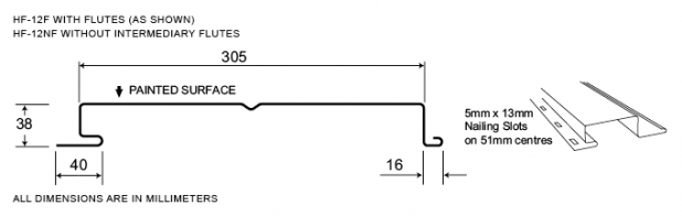
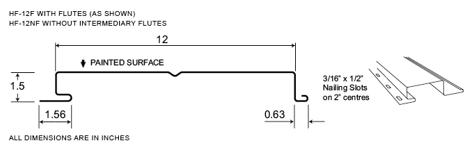
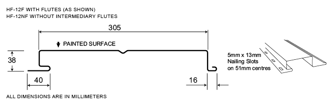
HF-12
HF-12, a popular choice among architects for a variety of institutional, industrial and commercial applications, is Agway’s most popular Hidden Fastener profile. With no visible fasteners, these 12” panels install easily and deliver the clean, sleek lines of contemporary surfaces,
Available in a range of gauges and a variety of standard and custom colours, HF-12 enables customers to specify the ideal combination of strength and aesthetics that optimize achievement of all project objectives.
Measurement Type
Profile Picture
1. Steel conforms to ASTM A653.
2. Section properties are in accordance with CSA-S136-07.
3. Values in row “S” are based on strength.
4. Values in row “D” are based on a deflection limit of 1/180 of the span.
5. Web crippling not included in strength values. See example calculation in notes to designer.
6. Oil canning may be present due to thickness and coverage. Oil canning is not a valid reason for rejection of this product.
7. Contact the sales department for stocked colours and gauges.
8. The load table contained on this data sheet was prepared by Dr. R.M. Schuster P.Eng. Professor Emeritus of Structural Engineering, University of Waterloo, Ontario, Canada.
1. Steel conforms to ASTM A653.
2. Section properties are in accordance with CSA-S136-07.
3. Values in row “S” are based on strength.
4. Values in row “D” are based on a deflection limit of 1/180 of the span.
5. Web crippling not included in strength values. See example calculation in notes to designer.
6. Oil canning may be present due to thickness and coverage. Oil canning is not a valid reason for rejection of this product.
7. Contact the sales department for stocked colours and gauges.
8. The load table contained on this data sheet was prepared by Dr. R.M. Schuster P.Eng. Professor Emeritus of Structural Engineering, University of Waterloo, Ontario, Canada.
Specifications
| GAUGE | LENGTH | COVERAGE | ||
|---|---|---|---|---|
| MINIMUM | MAXIMUM | MINIMUM | MAXIMUM | |
| 22 | 18 | 10 | 540 | 12 |
| GAUGE | LENGTH | COVERAGE | ||
|---|---|---|---|---|
| MINIMUM | MAXIMUM | MINIMUM | MAXIMUM | |
| 22 | 18 | 254 | 13.72 | 305 |
Section Properties
| BASE STEEL THICKNESS |
WEIGHT G90 |
YIELD STRESS |
SECTION MODULUS |
DEFLECTION MOMENT OF INERTIA |
|
|---|---|---|---|---|---|
| in | psf | ksi | MID SPAN in 3 |
SUPPORT in 3 |
MID SPAN in 4 |
| 0.030 | 1.87 | 33 | 0.0903 | 0.132 | 0.0817 |
| 0.036 | 2.23 | 33 | 0.120 | 0.158 | 0.106 |
| 0.048 | 2.96 | 33 | 0.184 | 0.210 | 0.163 |
| BASE STEEL THICKNESS |
MASS Z275 |
YIELD STRESS |
SECTION MODULUS |
DEFLECTION MOMENT OF INERTIA |
|
|---|---|---|---|---|---|
| mm | kg/m | MPa | MID SPAN x10 3mm3 |
SUPPORT x10 3mm3 |
MID SPAN x10 3mm3 |
| 0.762 | 8.85 | 230 | 4.84 | 7.10 | 0..111 |
| 0.914 | 10.6 | 230 | 6.45 | 8.50 | 0.144 |
| 1.22 | 14.2 | 230 | 9..88 | 11.3 | 0.221 |
