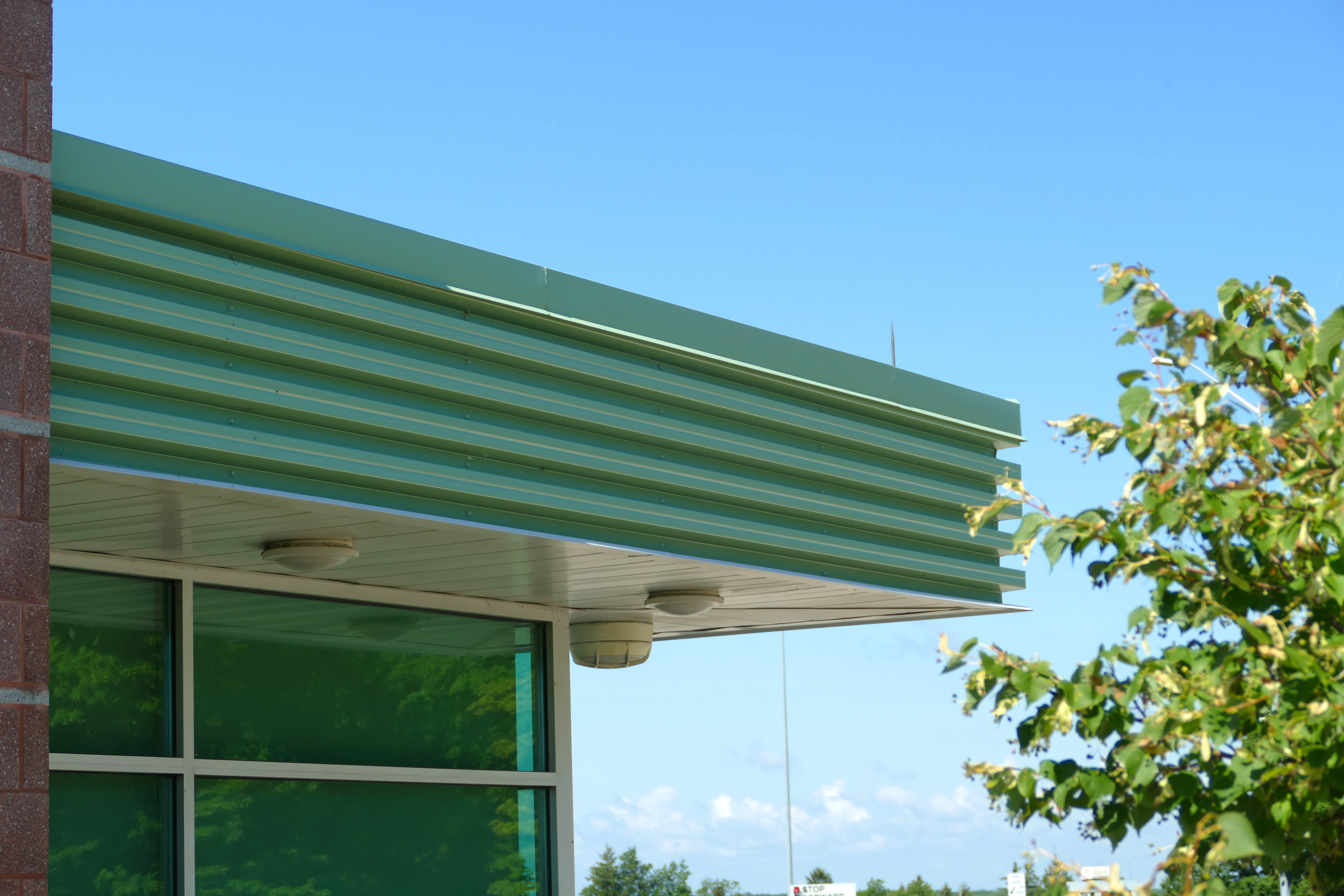
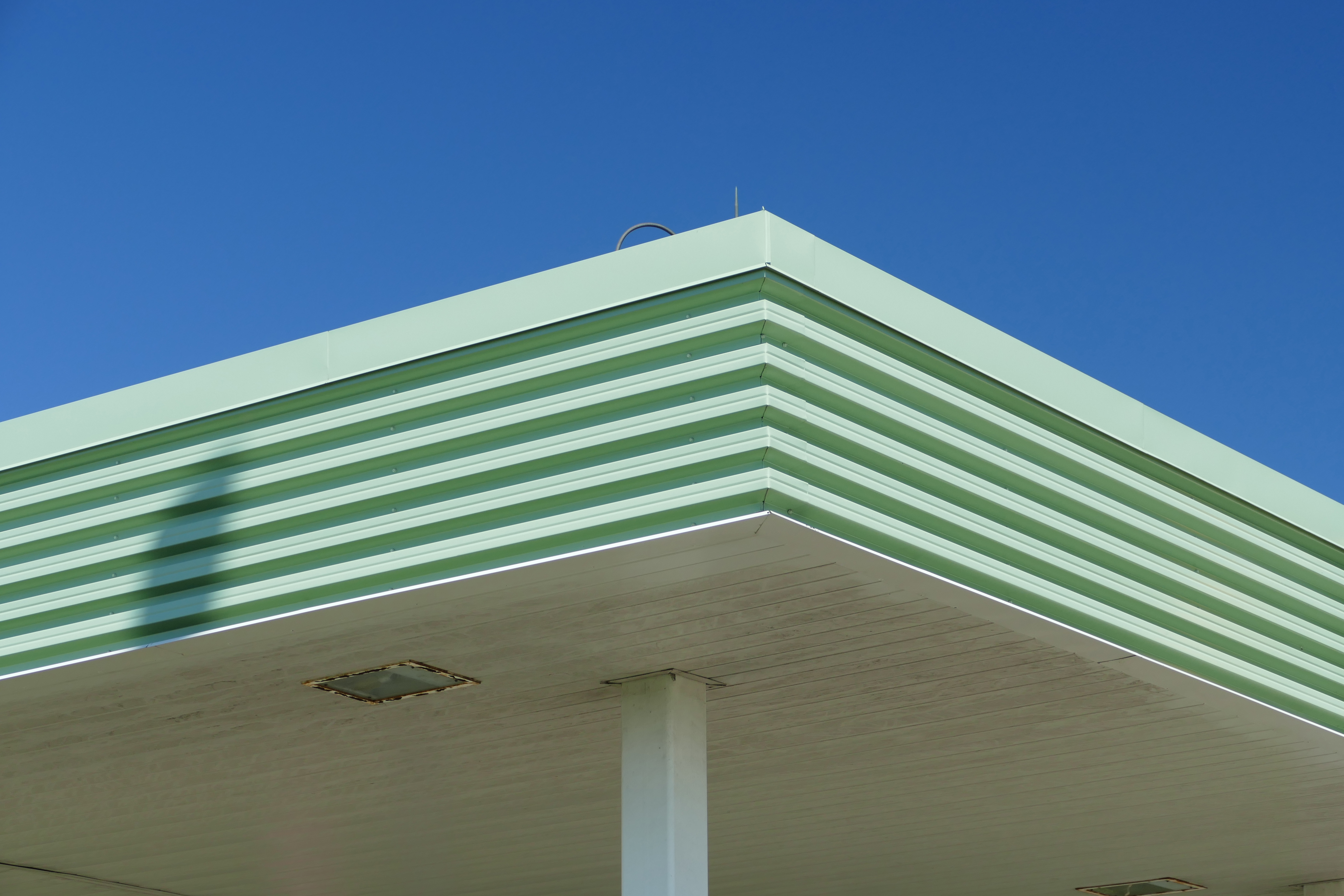
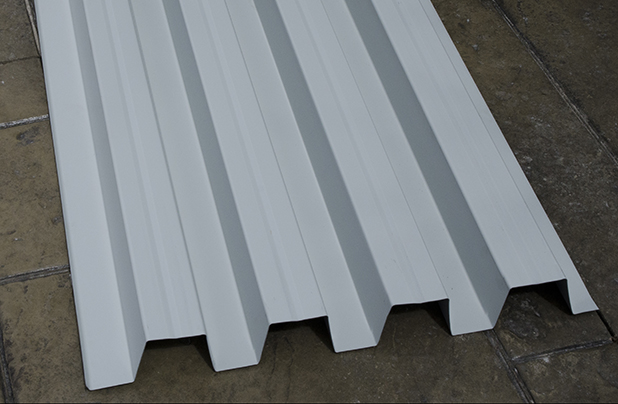
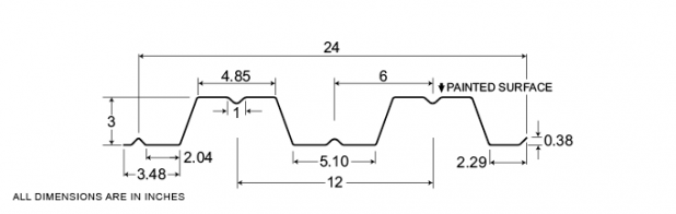
4-300
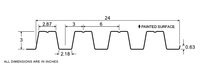
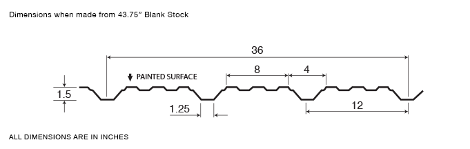
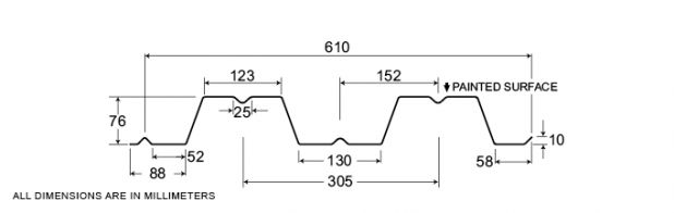
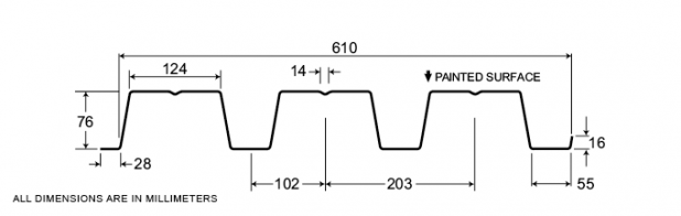
With a 3”panel depth and available in minimum 22 gauge, Agway’s 4-300 fluted panels provide 24” coverage and offer great strength and spanning capabilities, as well as a very bold and striking appearance.
Measurement Type
Profile Picture
1. Steel conforms to ASTM A653.
2. Section properties are in accordance with CSA-S136-07.
3. Values in row “S” are based on strength.
4. Values in row “D” are based on a deflection limit of 1/180 of the span.
5. Web crippling not included in strength values. See example calculation in notes to designer.
6. Contact the sales department for stocked colours and gauges.
7. The load table contained on this data sheet was prepared by Dr. R.M. Schuster P.Eng. Professor Emeritus of Structural Engineering, University of Waterloo, Ontario, Canada.
Specifications
| GAUGE | LENGTH | COVERAGE | ||
|---|---|---|---|---|
| MINIMUM | MAXIMUM | MINIMUM | MAXIMUM | |
| 22 | 16 | 48 | 600 | 24 |
| GAUGE | LENGTH | COVERAGE | ||
|---|---|---|---|---|
| MINIMUM | MAXIMUM | MINIMUM | MAXIMUM | |
| 22 | 16 | 1219.2 | 15.24 | 610 |
Section Properties
| BASE STEEL THICKNESS |
WEIGHT G90 |
YIELD STRESS |
SECTION MODULUS |
DEFLECTION MOMENT OF INERTIA |
|
|---|---|---|---|---|---|
| in | psf | ksi | MID SPAN in 3 |
SUPPORT in 3 |
MID SPAN in 4 |
| 0.030 | 2.32 | 33 | 0.485 | 0.492 | 0.866 |
| 0.036 | 2.78 | 33 | 0.621 | 0.624 | 1.07 |
| 0.048 | 3.68 | 33 | 0.882 | 0.898 | 1.46 |
| BASE STEEL THICKNESS |
MASS Z275 |
YIELD STRESS |
SECTION MODULUS |
DEFLECTION MOMENT OF INERTIA |
|
|---|---|---|---|---|---|
| mm | kg/m | MPa | MID SPAN x10 3mm3 |
SUPPORT x10 3mm3 |
MID SPAN x10 3mm3 |
| 0.762 | 11.3 | 230 | 26.0 | 26.4 | 1.18 |
| 0.914 | 13.6 | 230 | 33.3 | 33.4 | 1.46 |
| 1.22 | 18.0 | 230 | 47.4 | 48.2 | 2.00 |
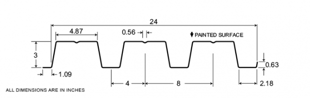
DR6-75
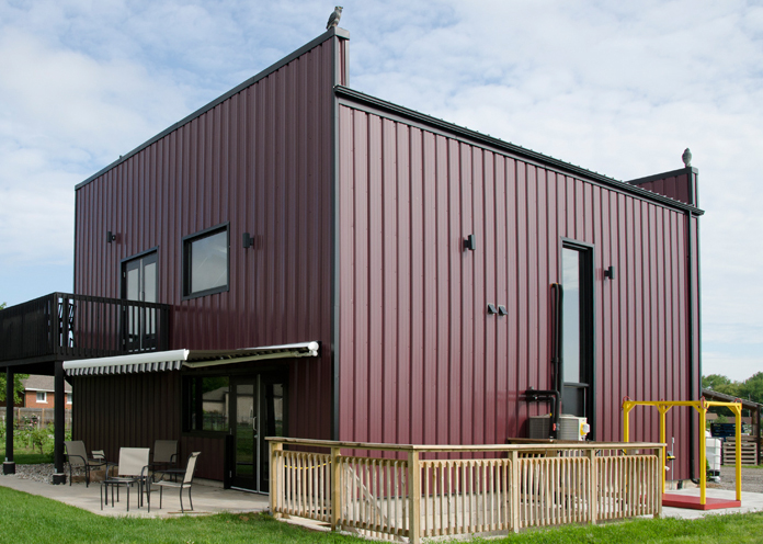
DR6-75 features an inverted Diamond profile, which presents a visually ‘softer’ finished look to surfaces. Available in 30 gauge to 24 gauge, Agway’s extremely popular and versatile Diamond Rib profiles can be used as wall cladding or interior liner panels, as well as for accent striping with other contiguous profiles. Diamond Rib is ideal for agricultural, industrial or commercial applications. Diamond Rib comes in a variety of colours and finishes.
Measurement Type
Profile Picture
1. Steel conforms to ASTM A653.
2. Section properties are in accordance with CSA-S136-07.
3. Values in row “S” are based on strength.
4. Values in row “D” are based on a deflection limit of 1/180 of the span.
5. Web crippling not included in strength values. See example calculation in notes to designer.
6. Contact the sales department for stocked colours and gauges.
7. The load table contained on this data sheet was prepared by Dr. R.M. Schuster P.Eng. Professor Emeritus of Structural Engineering, University of Waterloo, Ontario, Canada.
1. Steel conforms to ASTM A653.
2. Section properties are in accordance with CSA-S136-07.
3. Values in row “S” are based on strength.
4. Values in row “D” are based on a deflection limit of 1/180 of the span.
5. Web crippling not included in strength values. See example calculation in notes to designer.
6. Contact the sales department for stocked colours and gauges.
7. The load table contained on this data sheet was prepared by Dr. R.M. Schuster P.Eng. Professor Emeritus of Structural Engineering, University of Waterloo, Ontario, Canada.
Specifications
| GAUGE | LENGTH | COVERAGE | ||
|---|---|---|---|---|
| MINIMUM | MAXIMUM | MINIMUM | MAXIMUM | |
| 30 | 24 | 16 | 540 | 36 |
| GAUGE | LENGTH | COVERAGE | ||
|---|---|---|---|---|
| MINIMUM | MAXIMUM | MINIMUM | MAXIMUM | |
| 30 | 24 | 406 | 13.72 | 914 |
Section Properties
| BASE STEEL THICKNESS |
WEIGHT G90 |
YIELD STRESS |
SECTION MODULUS |
DEFLECTION MOMENT OF INERTIA |
|
|---|---|---|---|---|---|
| in | psf | ksi | MID SPAN in 3 |
SUPPORT in 3 |
MID SPAN in 4 |
| 0.0120 | 0.64 | 33 | 0.0202 | 0.0221 | 0.0098 |
| 0.0135 | 0.71 | 80 | 0.0208 | 0.0232 | 0.0102 |
| 0.0180 | 0.93 | 33 | 0.0361 | 0.0381 | 0.0182 |
| 0.0240 | 1.22 | 33 | 0.0498 | 0.0550 | 0.0268 |
| BASE STEEL THICKNESS |
MASS Z275 |
YIELD STRESS |
SECTION MODULUS |
DEFLECTION MOMENT OF INERTIA |
|
|---|---|---|---|---|---|
| mm | kg/m | MPa | MID SPAN x10 3mm3 |
SUPPORT x10 3mm3 |
MID SPAN x10 3mm3 |
| 0.305 | 3.11 | 230 | 1.09 | 1.19 | 0.0133 |
| 0.343 | 3.46 | 550 | 1.12 | 1.25 | 0.0140 |
| 0.457 | 4.52 | 230 | 1.94 | 2.04 | 0.0248 |
| 0.610 | 5.94 | 230 | 2.68 | 2.96 | 0.0366 |
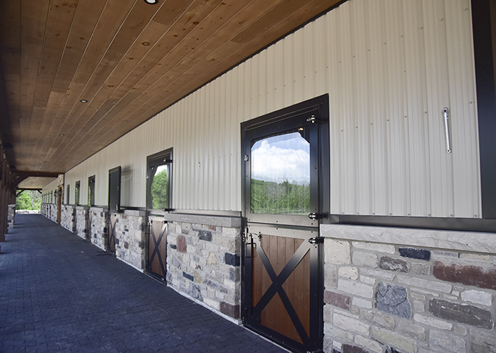
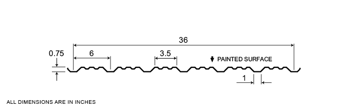
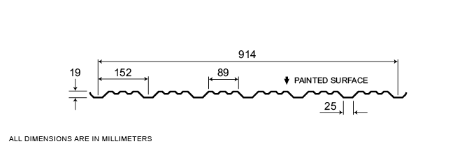
Diamond Rib
Available in 30 gauge to 22 gauge, Agway’s extremely popular and versatile Diamond Rib profiles can be used as wall cladding or interior liner panels, as well as accent striping with other as well as other contiguous profiles. Diamond Rib is ideal for agricultural, industrial or commercial applications.
Measurement Type
Profile Picture
1. Steel conforms to ASTM A653.
2. Section properties are in accordance with CSA-S136-07.
3. Values in row “S” are based on strength.
4. Values in row “D” are based on a deflection limit of 1/180 of the span.
5. Web crippling not included in strength values. See example calculation in notes to designer.
6. Contact the sales department for stocked colours and gauges.
7. The load table contained on this data sheet was prepared by Dr. R.M. Schuster P.Eng. Professor Emeritus of Structural Engineering, University of Waterloo, Ontario, Canada.
Specifications
| GAUGE | LENGTH | COVERAGE | ||
|---|---|---|---|---|
| MINIMUM | MAXIMUM | MINIMUM | MAXIMUM | |
| 30 | 24 | 16 | 540 | 36 |
| 30 | 22 | 16 | 480 | 30 |
| GAUGE | LENGTH | COVERAGE | ||
|---|---|---|---|---|
| MINIMUM | MAXIMUM | MINIMUM | MAXIMUM | |
| 30 | 22 | 406 | 13.72 | 914 |
| 30 | 22 | 406 | 12.92 | 780 |
Section Properties
| BASE STEEL THICKNESS |
WEIGHT G90 |
YIELD STRESS |
SECTION MODULUS |
DEFLECTION MOMENT OF INERTIA |
|
|---|---|---|---|---|---|
| in | psf | ksi | MID SPAN in 3 |
SUPPORT in 3 |
MID SPAN in 4 |
| 0.0120 | 0.64 | 33 | 0.0221 | 0.0202 | 0.0144 |
| 0.0135 | 0.71 | 80 | 0.0227 | 0.0203 | 0.0152 |
| 0.0180 | 0.93 | 33 | 0.0381 | 0.0361 | 0.0227 |
| 0.0240 | 1.22 | 33 | 0.0550 | 0.0498 | 0.0302 |
| 0.0300 | 1.51 | 33 | 0.0683 | 0.0637 | 0.0376 |
| BASE STEEL THICKNESS |
MASS Z275 |
YIELD STRESS |
SECTION MODULUS |
DEFLECTION MOMENT OF INERTIA |
|
|---|---|---|---|---|---|
| mm | kg/m | MPa | MID SPAN x10 3mm3 |
SUPPORT x10 3mm3 |
MID SPAN x10 3mm3 |
| 0.305 | 3.11 | 230 | 1.19 | 1.09 | 0.0196 |
| 0.343 | 3.46 | 550 | 1.22 | 1.09 | 0.0207 |
| 0.457 | 4.52 | 230 | 2.04 | 1.94 | 0.0309 |
| 0.610 | 5.94 | 230 | 2.96 | 2.68 | 0.0412 |
| 0.762 | 7.36 | 230 | 3.67 | 3.42 | 0.0514 |

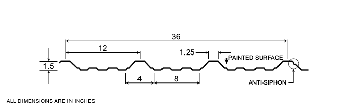
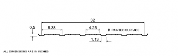
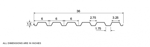
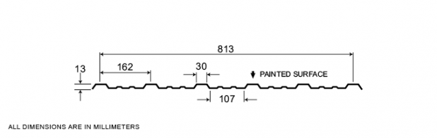
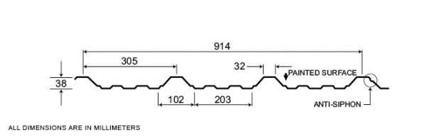
3-150
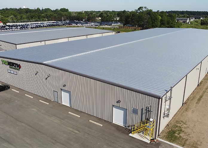
Ideal for both roof and wall applications, Agway 3-150 profile panels are extremely popular for pre-engineered buildings and are found in a wide variety of industrial and commercial applications. The 36” wide panels are available in a range of thickness and finishes.
Measurement Type
Profile Picture

1. Steel conforms to ASTM A653.
2. Section properties are in accordance with CSA-S136-07.
3. Values in row “S” are based on strength.
4. Values in row “D” are based on a deflection limit of 1/180 of the span.
5. Web crippling not included in strength values. See example calculation in notes to designer.
6. Contact the sales department for stocked colours and gauges.
7. The load table contained on this data sheet was prepared by Dr. R.M. Schuster P.Eng. Professor Emeritus of Structural Engineering, University of Waterloo, Ontario, Canada.
Specifications
| GAUGE | LENGTH | COVERAGE | ||
|---|---|---|---|---|
| MINIMUM | MAXIMUM | MINIMUM | MAXIMUM | |
| 29 | 22 | 10 | 828 | 36 |
| GAUGE | LENGTH | COVERAGE | ||
|---|---|---|---|---|
| MINIMUM | MAXIMUM | MINIMUM | MAXIMUM | |
| 29 | 22 | 254 | 21.03 | 914 |
Section Properties
| BASE STEEL THICKNESS |
WEIGHT G90 |
YIELD STRESS |
SECTION MODULUS |
DEFLECTION MOMENT OF INERTIA |
|
|---|---|---|---|---|---|
| in | psf | ksi | MID SPAN in 3 |
SUPPORT in 3 |
MID SPAN in 4 |
| 0.0180 | 0.95 | 33 | 0.0470 | 0.0539 | 0.0422 |
| 0.0240 | 1.25 | 33 | 0.0674 | 0.0777 | 0.0666 |
| 0.0300 | 1.55 | 33 | 0.0867 | 0.101 | 0.0911 |
| BASE STEEL THICKNESS |
MASS Z275 |
YIELD STRESS |
SECTION MODULUS |
DEFLECTION MOMENT OF INERTIA |
|
|---|---|---|---|---|---|
| mm | kg/m | MPa | MID SPAN x10 3mm3 |
SUPPORT x10 3mm3 |
MID SPAN x10 3mm3 |
| 0.457 | 4.64 | 230 | 2.52 | 2.90 | 0.0575 |
| 0.610 | 6.09 | 230 | 3.62 | 4.17 | 0.0908 |
| 0.762 | 7.54 | 230 | 4.66 | 5.45 | 0.124 |
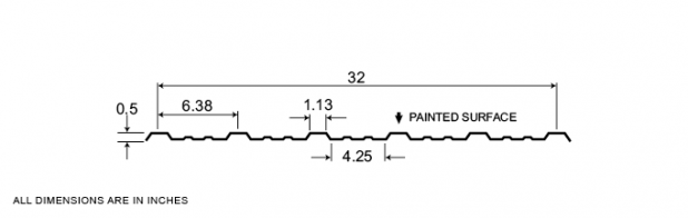
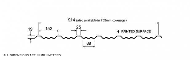
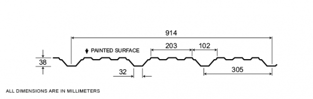
4-150
Ideal for both roof and wall applications, Agway 4-150 profile panels are extremely popular for pre-engineered buildings and can also be used in a wide variety of industrial and commercial applications. The 36” wide panels are available in a range of thickness and finishes.
Measurement Type
Profile Picture
1. Steel conforms to ASTM A653.
2. Section properties are in accordance with CSA-S136-07.
3. Values in row “S” are based on strength.
4. Values in row “D” are based on a deflection limit of 1/180 of the span.
5. Web crippling not included in strength values. See example calculation in notes to designer.
6. Contact the sales department for stocked colours and gauges.
7. The load table contained on this data sheet was prepared by Dr. R.M. Schuster P.Eng. Professor Emeritus of Structural Engineering, University of Waterloo, Ontario, Canada.
Specifications
| GAUGE | LENGTH | COVERAGE | ||
|---|---|---|---|---|
| MINIMUM | MAXIMUM | MINIMUM | MAXIMUM | |
| 29 | 22 | 10 | 828 | 36 |
| GAUGE | LENGTH | COVERAGE | ||
|---|---|---|---|---|
| MINIMUM | MAXIMUM | MINIMUM | MAXIMUM | |
| 29 | 22 | 254 | 21.03 | 914 |
Section Properties
| BASE STEEL THICKNESS |
WEIGHT G90 |
YIELD STRESS |
SECTION MODULUS |
DEFLECTION MOMENT OF INERTIA |
|
|---|---|---|---|---|---|
| in | psf | ksi | MID SPAN in 3 |
SUPPORT in 3 |
MID SPAN in 4 |
| 0.0135 | 0.73 | 80 | 0.0340 | 0.0278 | 0.0455 |
| 0.0150 | 0.80 | 33 | 0.0428 | 0.0364 | 0.0564 |
| 0.0180 | 0.95 | 50 | 0.0509 | 0.0432 | 0.0673 |
| 0.0240 | 1.25 | 33 | 0.0777 | 0.0674 | 0.0938 |
| 0.0300 | 1.55 | 33 | 0.101 | 0.0867 | 0.117 |
| BASE STEEL THICKNESS |
MASS Z275 |
YIELD STRESS |
SECTION MODULUS |
DEFLECTION MOMENT OF INERTIA |
|
|---|---|---|---|---|---|
| mm | kg/m | MPa | MID SPAN x10 3mm3 |
SUPPORT x10 3mm3 |
MID SPAN x10 3mm3 |
| 0.343 | 3.55 | 550 | 1.83 | 1.49 | 0.0621 |
| 0.381 | 3.91 | 230 | 2.30 | 1.95 | 0.0769 |
| 0.457 | 4.64 | 345 | 2.74 | 2.32 | 0.0919 |
| 0.610 | 6.09 | 230 | 4.17 | 3.62 | 0.128 |
| 0.762 | 7.54 | 230 | 5.45 | 4.66 | 0.160 |
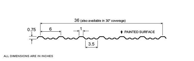
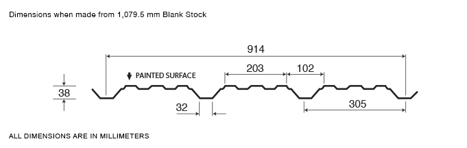
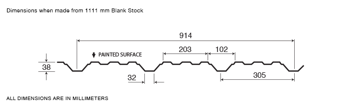
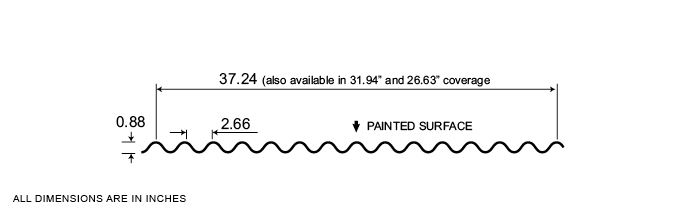
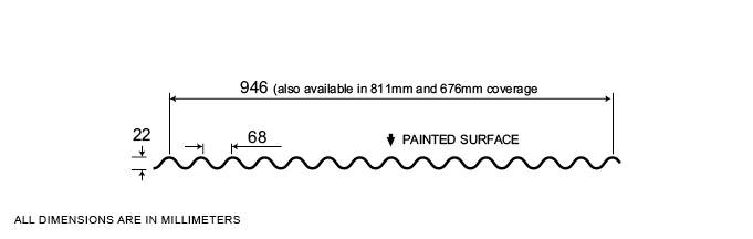
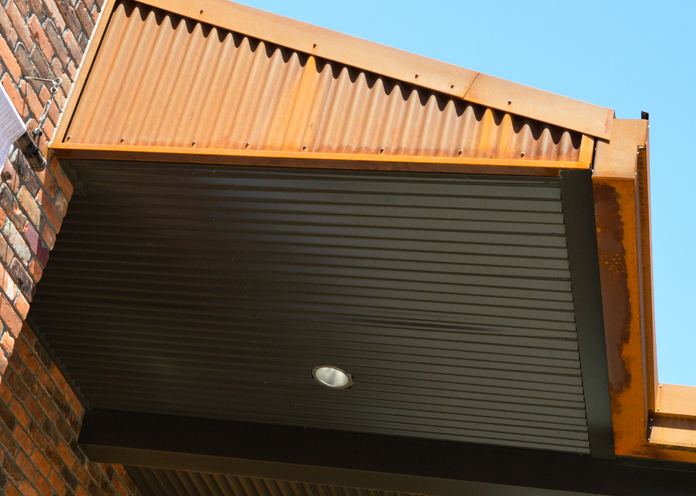
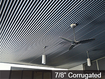
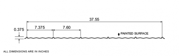
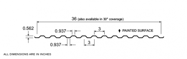
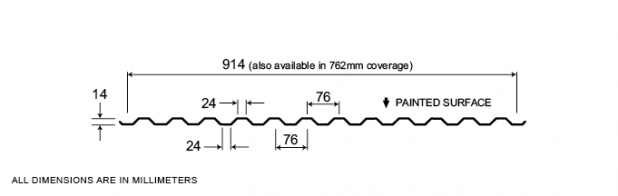
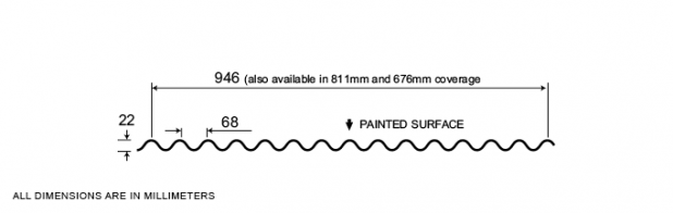
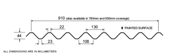
7/8″ Corrugated
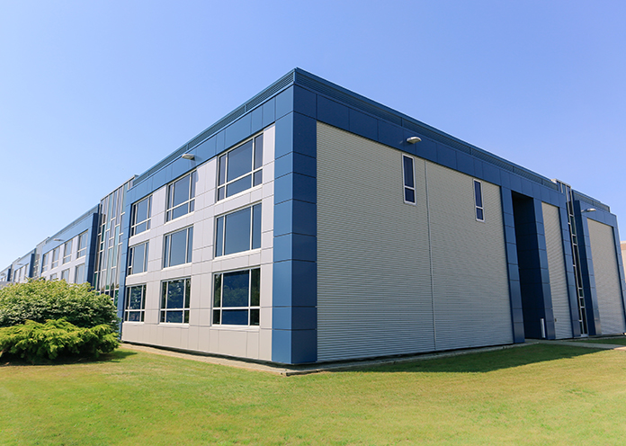
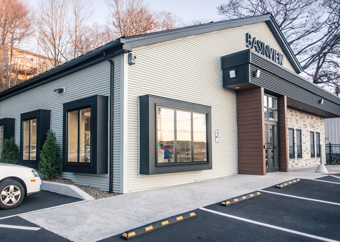
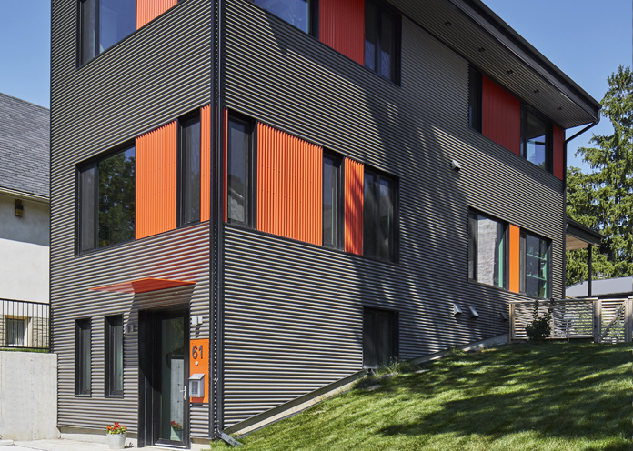
Very popular among architects, Agway’s 7/8” Corrugated profile features panels with exposed fasteners and no hard lines, resulting in a highly consistent appearance and a more organic overall look. Panels are available in a variety of widths, thicknesses and finishes.
Measurement Type
Profile Picture
1. Steel conforms to ASTM A653.
2. Section properties are in accordance with CSA-S136-07.
3. Values in row “S” are based on strength.
4. Values in row “D” are based on a deflection limit of 1/180 of the span.
5. Web crippling not included in strength values. See example calculation in notes to designer.
6. Contact the sales department for stocked colours and gauges.
7. The load table contained on this data sheet was prepared by Dr. R.M. Schuster P.Eng. Professor Emeritus of Structural Engineering, University of Waterloo, Ontario, Canada.
Specifications
| GAUGE | LENGTH | COVERAGE | ||
|---|---|---|---|---|
| MINIMUM | MAXIMUM | MINIMUM | MAXIMUM | |
| 28 | 18 | 30 | 780 | 37.25 |
| 28 | 18 | 30 | 780 | 31.94 |
| 30 | 18 | 30 | 780 | 26.59 |
| GAUGE | LENGTH | COVERAGE | ||
|---|---|---|---|---|
| MINIMUM | MAXIMUM | MINIMUM | MAXIMUM | |
| 28 | 18 | 762 | 19.81 | 946.2 |
| 28 | 18 | 762 | 19.81 | 811.28 |
| 30 | 18 | 762 | 19.81 | 675.39 |
Section Properties
| BASE STEEL THICKNESS |
WEIGHT G90 |
YIELD STRESS |
SECTION MODULUS |
DEFLECTION MOMENT OF INERTIA |
|
|---|---|---|---|---|---|
| in | psf | ksi | MID SPAN in 3 |
SUPPORT in 3 |
MID SPAN in 4 |
| 0.018 | 1.00 | 33 | 0.0566 | 0.0566 | 0.0248 |
| 0.024 | 1.32 | 33 | 0.0743 | 0.0743 | 0.0325 |
| 0.030 | 1.64 | 33 | 0.0913 | 0.0913 | 0.0399 |
| 0.036 | 1.95 | 33 | 0.108 | 0.108 | 0.0471 |
| 0.048 | 2.58 | 33 | 0.139 | 0.139 | 0.0607 |
| BASE STEEL THICKNESS |
MASS Z275 |
YIELD STRESS |
SECTION MODULUS |
DEFLECTION MOMENT OF INERTIA |
|
|---|---|---|---|---|---|
| mm | kg/m | MPa | MID SPAN x10 3mm3 |
SUPPORT x10 3mm3 |
MID SPAN x10 3mm3 |
| 0.457 | 4.90 | 230 | 3.04 | 3.04 | 0.0338 |
| 0.610 | 6.44 | 230 | 3.99 | 3.99 | 0.0444 |
| 0.762 | 7.99 | 230 | 4.91 | 4.91 | 0.0545 |
| 0.914 | 9.53 | 230 | 5.79 | 5.79 | 0.0643 |
| 1.22 | 12.6 | 230 | 7.46 | 7.46 | 0.0829 |
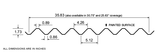
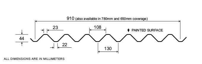
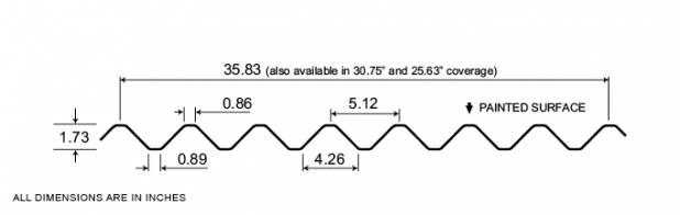
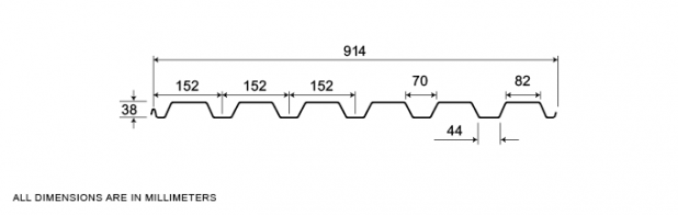
7-175
A traditional profile in Agway’s Exposed Fastener Series, our 7-175 panels are a popular choice for many industrial and commercial building applications. Panel options offer a choice of 35.83”, 30.75” and 25.63” coverage, in a variety of thicknesses and finishes.
Measurement Type
Profile Picture
1. Steel conforms to ASTM A653.
2. Section properties are in accordance with CSA-S136-07.
3. Values in row “S” are based on strength.
4. Values in row “D” are based on a deflection limit of 1/180 of the span.
5. Web crippling not included in strength values. See example calculation in notes to designer.
6. Contact the sales department for stocked colours and gauges.
7. The load table contained on this data sheet was prepared by Dr. R.M. Schuster P.Eng. Professor Emeritus of Structural Engineering, University of Waterloo, Ontario, Canada.
1. Steel conforms to ASTM A653.
2. Section properties are in accordance with CSA-S136-07.
3. Values in row “S” are based on strength.
4. Values in row “D” are based on a deflection limit of 1/180 of the span.
5. Web crippling not included in strength values. See example calculation in notes to designer.
6. Contact the sales department for stocked colours and gauges.
7. The load table contained on this data sheet was prepared by Dr. R.M. Schuster P.Eng. Professor Emeritus of Structural Engineering, University of Waterloo, Ontario, Canada.
Specifications
| GAUGE | LENGTH | COVERAGE | ||
|---|---|---|---|---|
| MINIMUM | MAXIMUM | MINIMUM | MAXIMUM | |
| 26 | 18 | 10 | 780 | 36 |
| 26 | 18 | 10 | 780 | 30.75 |
| 26 | 18 | 10 | 780 | 25.56 |
| GAUGE | LENGTH | COVERAGE | ||
|---|---|---|---|---|
| MINIMUM | MAXIMUM | MINIMUM | MAXIMUM | |
| 26 | 18 | 254 | 19.81 | 914.4 |
| 26 | 18 | 254 | 19.81 | 781.1 |
| 26 | 18 | 254 | 19.81 | 649.2 |
Section Properties
| BASE STEEL THICKNESS |
WEIGHT G90 |
YIELD STRESS |
SECTION MODULUS |
DEFLECTION MOMENT OF INERTIA |
|
|---|---|---|---|---|---|
| in | psf | ksi | MID SPAN in 3 |
SUPPORT in 3 |
MID SPAN in 4 |
| 0.018 | 1.04 | 33 | 0.118 | 0.118 | 0.104 |
| 0.024 | 1.36 | 33 | 0.158 | 0.158 | 0.138 |
| 0.030 | 1.69 | 33 | 0.198 | 0.196 | 0.173 |
| 0.036 | 2.02 | 33 | 0.234 | 0.234 | 0.207 |
| 0.048 | 2.67 | 33 | 0.309 | 0.309 | 0.275 |
| BASE STEEL THICKNESS |
MASS Z275 |
YIELD STRESS |
SECTION MODULUS |
DEFLECTION MOMENT OF INERTIA |
|
|---|---|---|---|---|---|
| mm | kg/m | MPa | MID SPAN x10 3mm3 |
SUPPORT x10 3mm3 |
MID SPAN x10 3mm3 |
| 0.457 | 5.06 | 230 | 6.34 | 6.33 | 0.142 |
| 0.610 | 6.66 | 230 | 8.47 | 8.47 | 0.189 |
| 0.762 | 8.25 | 230 | 10.5 | 10.5 | 0.236 |
| 0.914 | 9.85 | 230 | 12.6 | 12.6 | 0.282 |
| 1.22 | 13.0 | 230 | 16.6 | 16.6 | 0.375 |
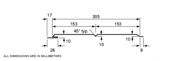
Product Sheet
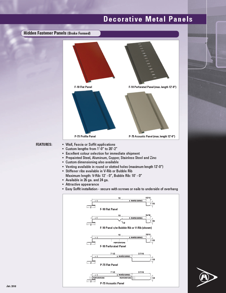
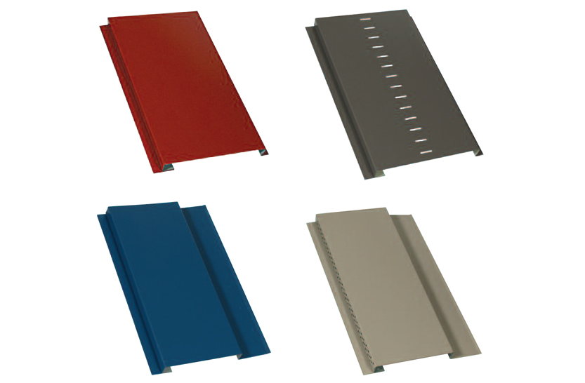
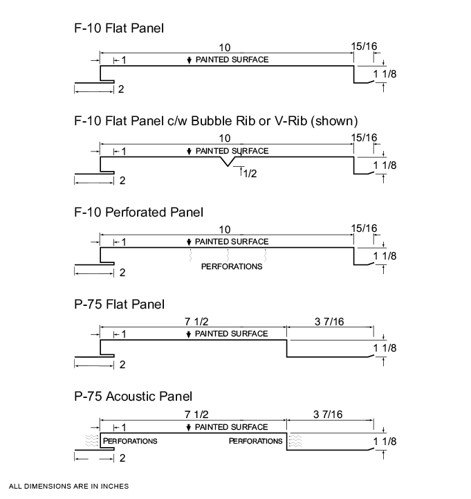
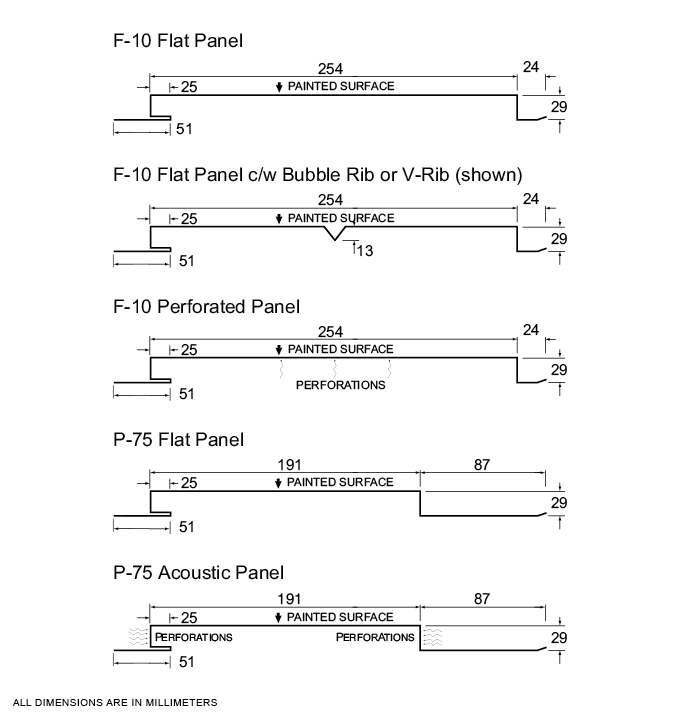
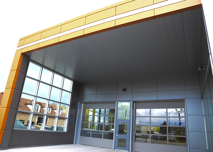
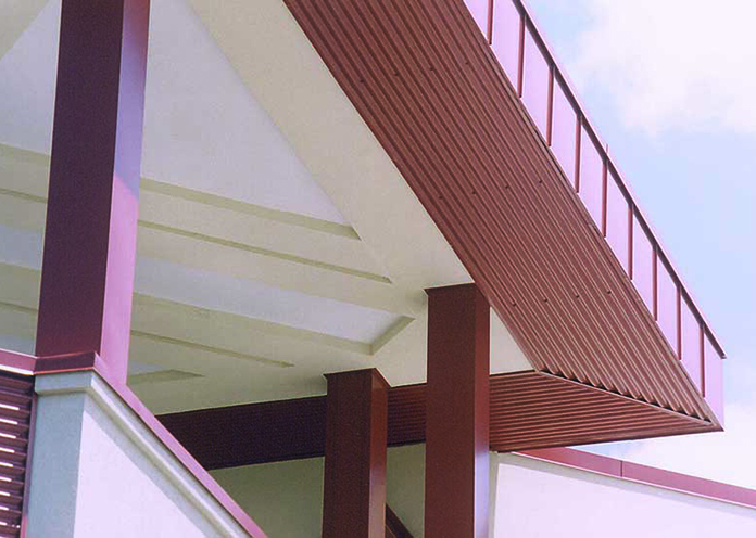
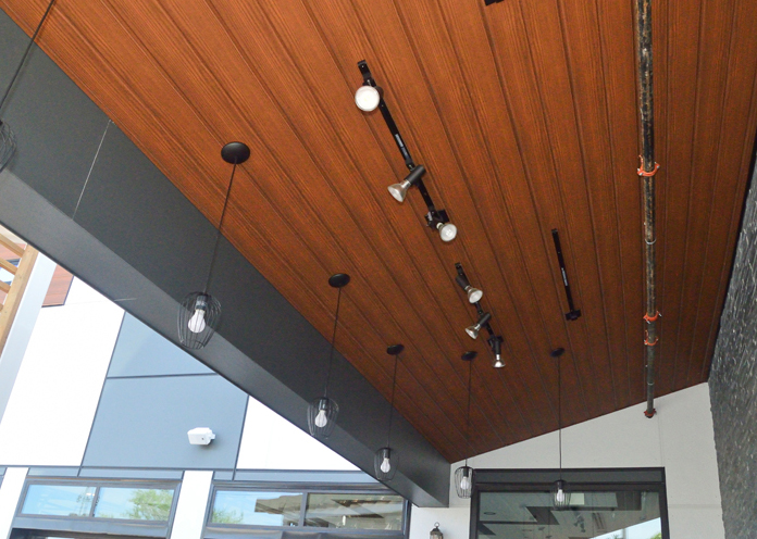
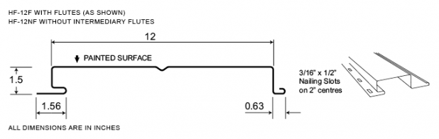
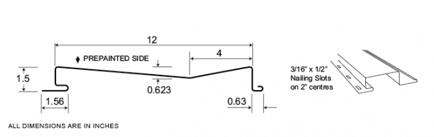
Decorative Metal Panels
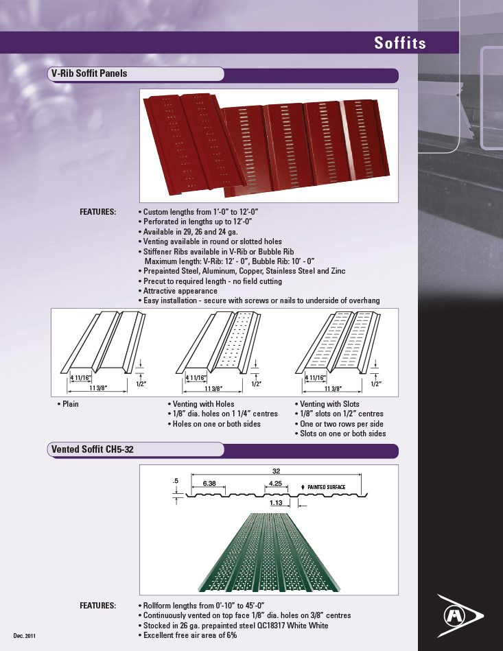
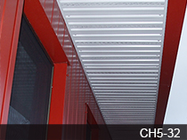
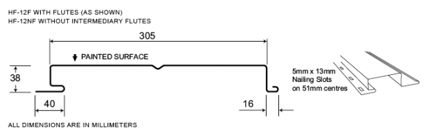
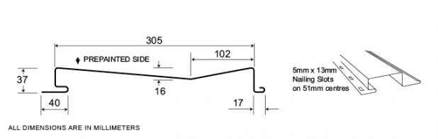
For walls, fascia, or soffits, Agway’s complete line of Hidden Fastener Decorative Metal Panels is ideal for a variety of applications. Available for immediate shipment, these decorative panels are available in custom lengths up to 20’ in a range of colours, and in vented (round or slotted holes) or non-vented variants.
Measurement Type
Profile Picture
- Wall, Fascia or Soffit applications
- Custom lengths from 1’-0” to 20’-2”
- Excellent colour selection for immediate shipment
- Prepainted Steel, Aluminum, Copper, Stainless Steel and Zinc
- Custom dimensioning also available
- Venting available in round or slotted holes
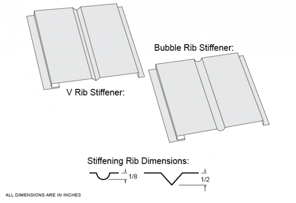
- Stiffener ribs available in V-Rib or Bubble Rib
Maximum length: V-Rib: 12’ – 0”, Bubble Rib: 10’ – 0” - Available in 26 ga. and 24 ga.
- Attractive appearance
- Easy Soffit installation – secure with screws or nails to underside of overhang
V-Rib and Bubble Rib Stiffeners
Flashings and Trims F-10/P-75
- Wall, Fascia or Soffit applications
- Custom lengths from 0.31m to 6.2m
- Excellent colour selection for immediate shipment
- Prepainted Steel, Aluminum, Copper, Stainless Steel and Zinc
- Custom dimensioning also available
- Venting available in round or slotted holes
- Stiffener ribs available in V-Rib or Bubble Rib
Maximum length: V-Rib: 3.7m, Bubble Rib: 3.1m - Available in 26 ga. and 24 ga.
- Attractive appearance
- Easy Soffit installation – secure with screws or nails to underside of overhang
V-Rib and Bubble Rib Stiffeners

Flashings and Trims F-10/P-75
Product Sheet
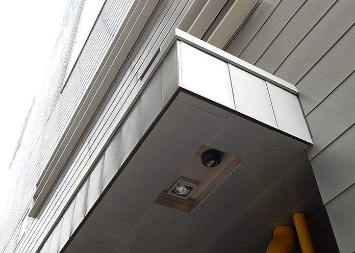
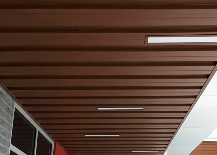
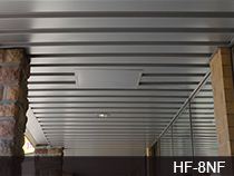
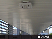
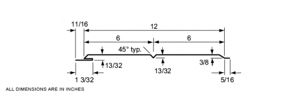
ICI Soffits
Easy to handle and install with multiple products to choose from (including custom flat panels), Agway’s ICI soffit panels are available in custom lengths and a full choice of stock or custom colours and finishes.
- Multiple products to choose from including custom flat panels
- Full choice of any stock or custom colour
- Plain or Pre-painted Steel, Aluminum, Copper, Stainless Steel, Rheinzink and Indaten
- Pre-cut to required length – no field cutting
- Attractive appearance
- Easy installation – Exposed or Hidden fastener profiles available
- Perforated or Non-Perforated available
Measurement Type
Product Sheet
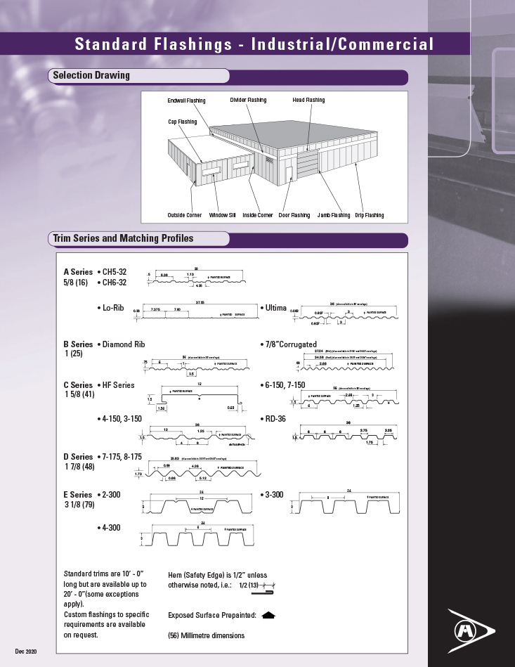
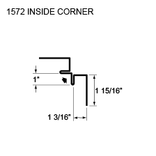
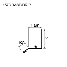
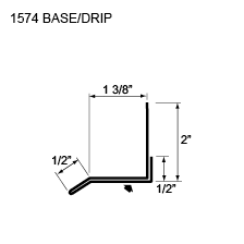
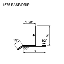
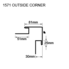
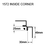
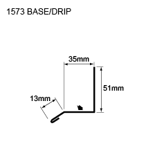
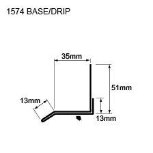
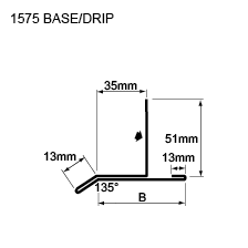
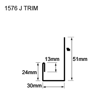
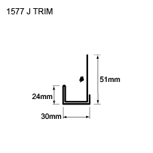
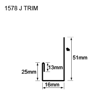
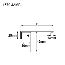
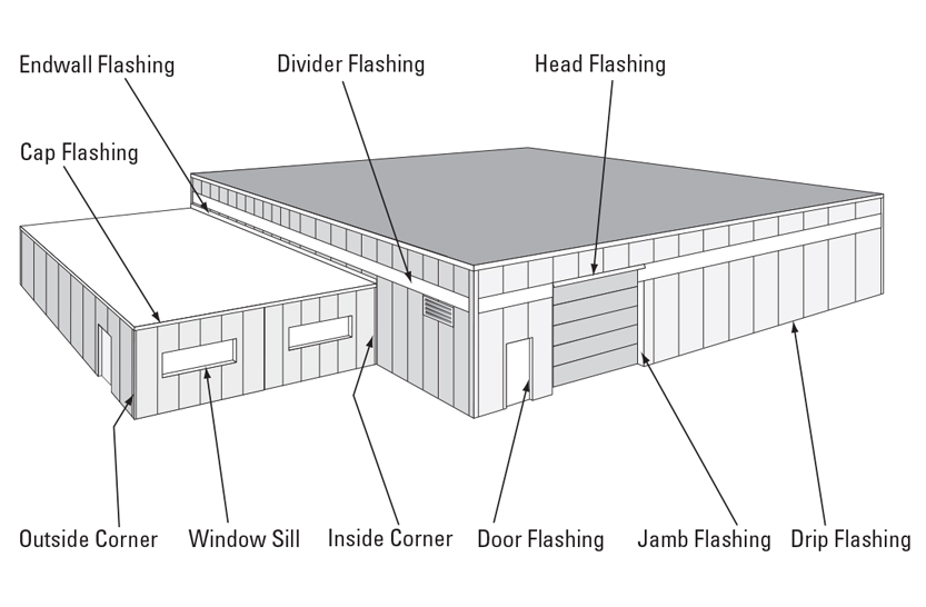
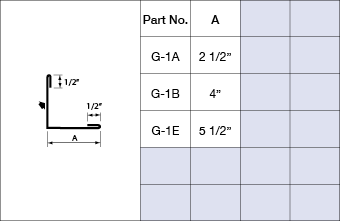
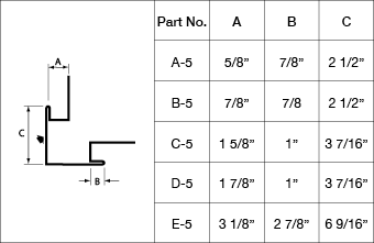
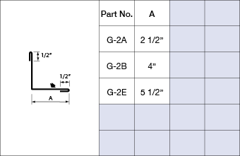
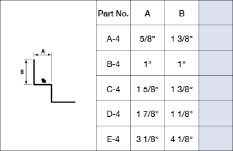
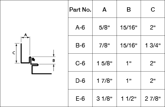
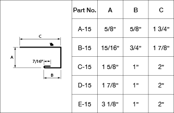
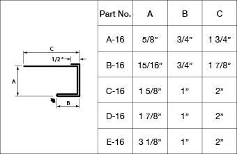
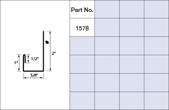
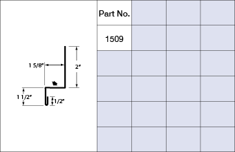
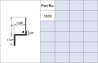
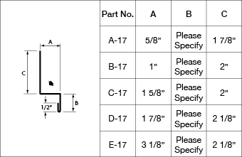
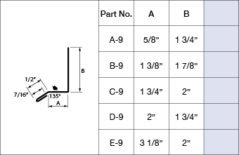
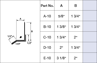
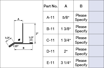
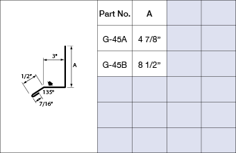
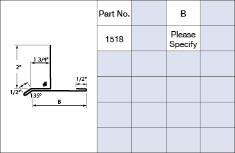
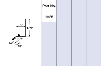
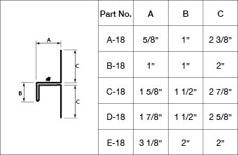
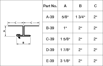
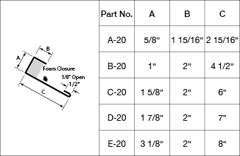
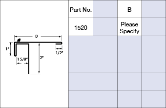
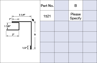
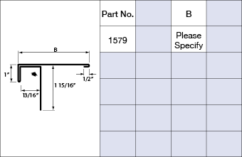
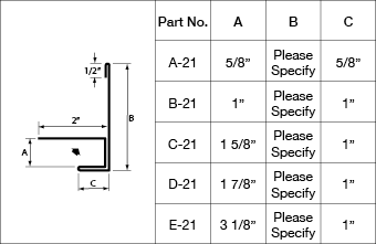
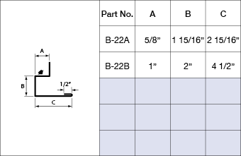
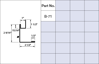
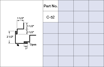
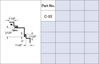
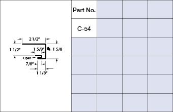
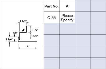
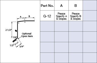
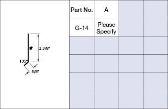
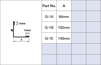
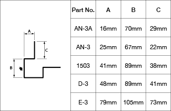
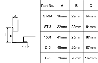
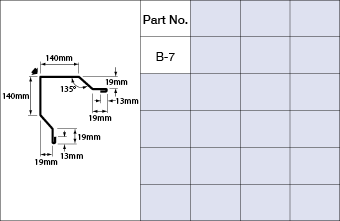
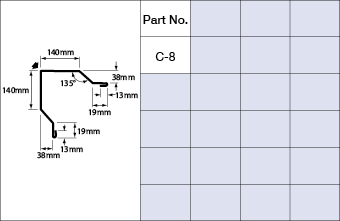
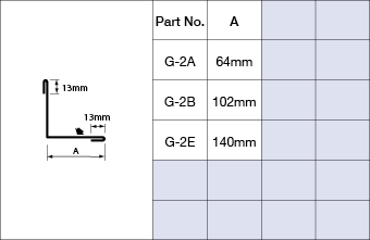
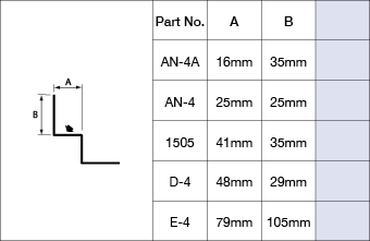
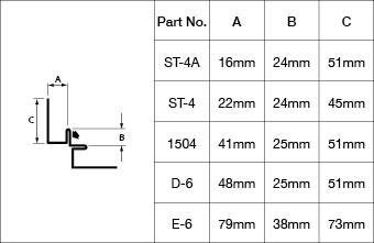
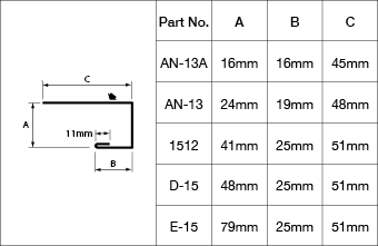
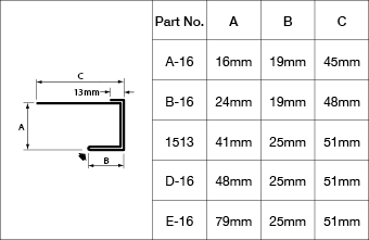
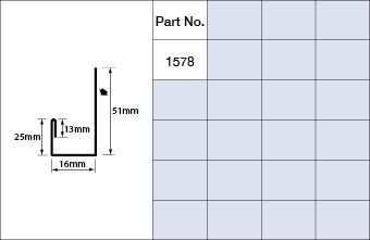
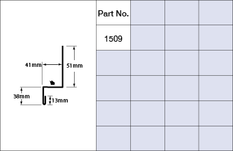
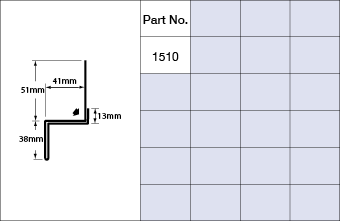
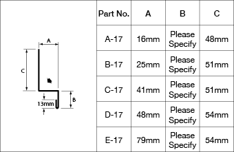
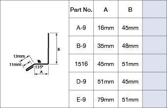
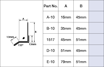
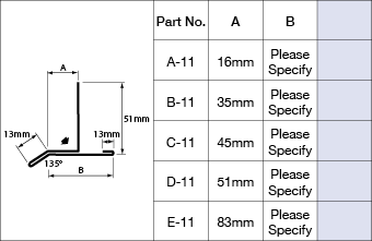
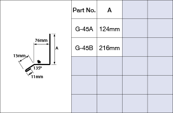
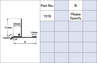
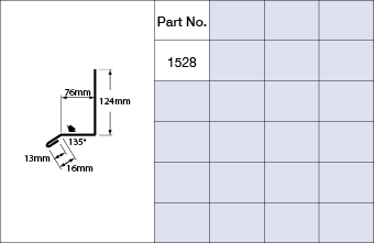
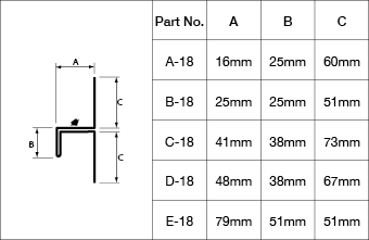
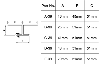
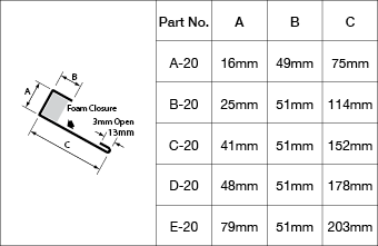
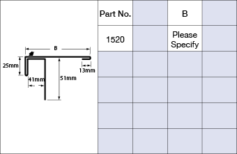
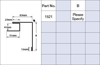
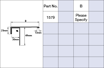
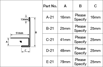
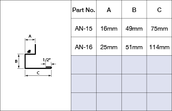
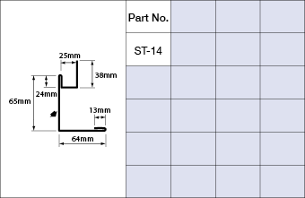
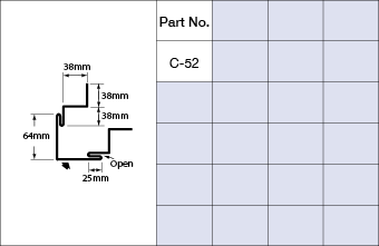
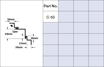
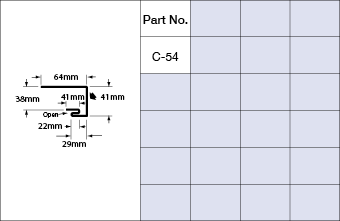
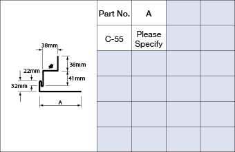
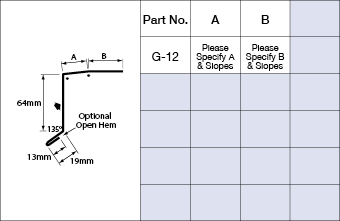
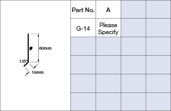
Standard Flashings ICI
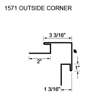
If there is a shape of flashing you need, we can bend it. Agway offers everything required in flashings and trims to complete your industrial and/or commercial building installation. From Outside Corners to Jambs & Coping Flashing, Agway has it all.
Measurement Type
Profile Picture
A SERIES 5/8 in
B SERIES 1 in


C SERIES 1 5/8 in


D SERIES 1 7/8 in

E SERIES 3 1/8 in

Typical Flashings
OUTSIDE CORNERS
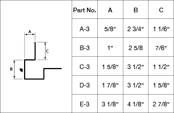


INSIDE CORNERS
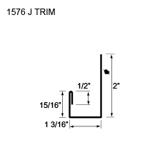
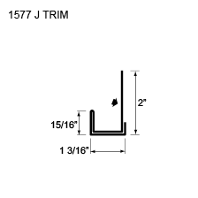
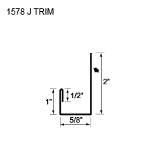
J-TRIMS
BASE TRIMS
DRIPS
DIVIDERS
TOP CLOSURES
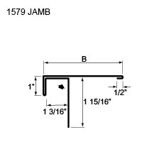
JAMBS
HIDDEN FASTENERS
WINDOW SILLS
A SERIES 16 mm

B SERIES 25 mm
C SERIES 41 mm

D SERIES 48 mm

E SERIES 79 mm

Typical Flashings
OUTSIDE CORNERS
INSIDE CORNERS
J-TRIMS
BASE TRIMS
DRIPS
DIVIDERS
TOP CLOSURES
JAMBS
HIDDEN FASTENERS
WINDOW SILLS

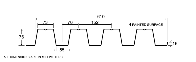
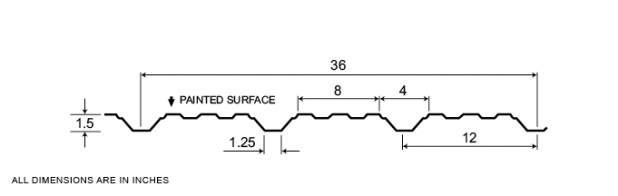
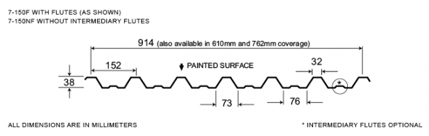
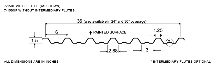
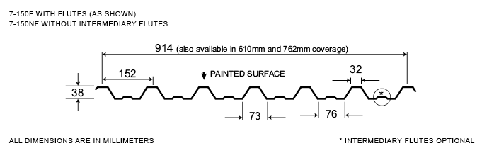
7-150
An Exposed Fastener System, the 7-150 profile demonstrates the versatility of Agway profile designs as it can be used as a roof or wall cladding. Moreover, its load bearing capabilities enable 7-150 system components to function as a structural members. An economical system that’s very easy to install have made 7-150 a popular choice for industrial and commercial applications.
Agway 7-150 comes in a full range of stock colours, with colour matched fasteners, trims and accessories.
Measurement Type
Profile Picture
1. Steel conforms to ASTM A653.
2. Section properties are in accordance with CSA-S136-07.
3. Values in row “S” are based on strength.
4. Values in row “D” are based on a deflection limit of 1/180 of the span.
5. Web crippling not included in strength values. See example calculation in notes to designer.
6. Contact the sales department for stocked colours and gauges.
7. The load table contained on this data sheet was prepared by Dr. R.M. Schuster P.Eng. Professor Emeritus of Structural Engineering, University of Waterloo, Ontario, Canada.
Specifications
| GAUGE | LENGTH | COVERAGE | ||
|---|---|---|---|---|
| MINIMUM | MAXIMUM | MINIMUM | MAXIMUM | |
| 26 | 20 | 10 | 780 | 36 |
| 26 | 20 | 10 | 780 | 30 |
| 26 | 20 | 10 | 780 | 24 |
| GAUGE | LENGTH | COVERAGE | ||
|---|---|---|---|---|
| MINIMUM | MAXIMUM | MINIMUM | MAXIMUM | |
| 26 | 20 | 254 | 19.81 | 914 |
| 26 | 20 | 254 | 19.81 | 780 |
| 26 | 20 | 254 | 19.81 | 610 |
Section Properties
| BASE STEEL THICKNESS |
WEIGHT G90 |
YIELD STRESS |
SECTION MODULUS |
DEFLECTION MOMENT OF INERTIA |
|
|---|---|---|---|---|---|
| in | psf | ksi | MID SPAN in 3 |
SUPPORT in 3 |
MID SPAN in 4 |
| 0.018 | 1.04 | 33 | 0.0940 | 0.0888 | 0.0985 |
| 0.024 | 1.36 | 33 | 0.136 | 0.127 | 0.132 |
| 0.030 | 1.69 | 33 | 0.175 | 0.162 | 0.165 |
| 0.036 | 2.02 | 33 | 0.208 | 0.198 | 0.197 |
| BASE STEEL THICKNESS |
MASS Z275 |
YIELD STRESS |
SECTION MODULUS |
DEFLECTION MOMENT OF INERTIA |
|
|---|---|---|---|---|---|
| mm | kg/m | MPa | MID SPAN x10 3mm3 |
SUPPORT x10 3mm3 |
MID SPAN x10 3mm3 |
| 0.457 | 5.06 | 230 | 5.05 | 4.77 | 0.134 |
| 0.610 | 6.66 | 230 | 7.28 | 6.82 | 0.180 |
| 0.762 | 8.25 | 230 | 9.38 | 8.73 | 0.225 |
| 0.914 | 9.85 | 230 | 11.2 | 10.7 | 0.270 |
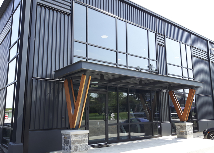
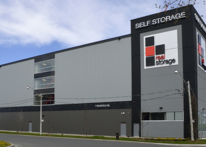
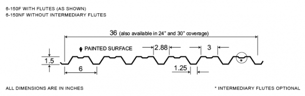
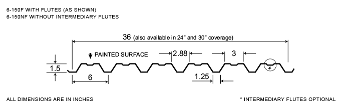
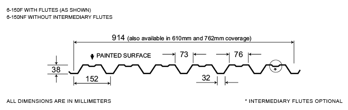
6-150
Widely used in industrial and commercial building applications, Agway 6-150 is the most widely used of our Exposed Fastener Series. Panels are available in 24″, 30” and 36” coverage, in a variety of thicknesses and finishes.
Measurement Type
Profile Picture
1. Steel conforms to ASTM A653.
2. Section properties are in accordance with CSA-S136-07.
3. Values in row “S” are based on strength.
4. Values in row “D” are based on a deflection limit of 1/180 of the span.
5. Web crippling not included in strength values. See example calculation in notes to designer.
6. Contact the sales department for stocked colours and gauges.
7. The load table contained on this data sheet was prepared by Dr. R.M. Schuster P.Eng. Professor Emeritus of Structural Engineering, University of Waterloo, Ontario, Canada.
1. Steel conforms to ASTM A653.
2. Section properties are in accordance with CSA-S136-07.
3. Values in row “S” are based on strength.
4. Values in row “D” are based on a deflection limit of 1/180 of the span.
5. Web crippling not included in strength values. See example calculation in notes to designer.
6. Contact the sales department for stocked colours and gauges.
7. The load table contained on this data sheet was prepared by Dr. R.M. Schuster P.Eng. Professor Emeritus of Structural Engineering, University of Waterloo, Ontario, Canada.
Specifications
| GAUGE | LENGTH | COVERAGE | ||
|---|---|---|---|---|
| MINIMUM | MAXIMUM | MINIMUM | MAXIMUM | |
| 26 | 20 | 10 | 780 | 36 |
| 26 | 20 | 10 | 780 | 30 |
| 26 | 20 | 10 | 780 | 24 |
| GAUGE | LENGTH | COVERAGE | ||
|---|---|---|---|---|
| MINIMUM | MAXIMUM | MINIMUM | MAXIMUM | |
| 26 | 20 | 254 | 19.81 | 914 |
| 26 | 20 | 254 | 19.81 | 780 |
| 26 | 20 | 254 | 19.81 | 610 |
Section Properties
| BASE STEEL THICKNESS |
WEIGHT G90 |
YIELD STRESS |
SECTION MODULUS |
DEFLECTION MOMENT OF INERTIA |
|
|---|---|---|---|---|---|
| in | psf | ksi | MID SPAN in 3 |
SUPPORT in 3 |
MID SPAN in 4 |
| 0.018 | 1.04 | 33 | 0.0888 | 0.0940 | 0.0796 |
| 0.024 | 1.36 | 33 | 0.127 | 0.136 | 0.119 |
| 0.030 | 1.69 | 33 | 0.162 | 0.175 | 0.157 |
| 0.036 | 2.02 | 33 | 0.198 | 0.208 | 0.194 |
| BASE STEEL THICKNESS |
MASS Z275 |
YIELD STRESS |
SECTION MODULUS |
DEFLECTION MOMENT OF INERTIA |
|
|---|---|---|---|---|---|
| mm | kg/m | MPa | MID SPAN x10 3mm3 |
SUPPORT x10 3mm3 |
MID SPAN x10 3mm3 |
| 0.457 | 5.06 | 230 | 4.77 | 5.06 | 0.108 |
| 0.610 | 6.66 | 230 | 6.82 | 7.28 | 0.162 |
| 0.762 | 8.25 | 230 | 8.73 | 9.38 | 0.214 |
| 0.914 | 9.85 | 230 | 10.7 | 11.2 | 0.265 |
